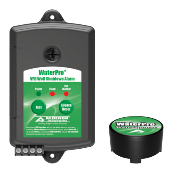
Alderon Industries WaterPro WaterSpotter 8073 Manuale di funzionamento, manutenzione e installazione
Sfoglia online o scarica il pdf Manuale di funzionamento, manutenzione e installazione per Sistema di sicurezza Alderon Industries WaterPro WaterSpotter 8073. Alderon Industries WaterPro WaterSpotter 8073 4.

WaterPro
AVFD Series Alarm
™
WaterPro
WaterSpotter
™
Part Number - 8073
Operation, Maintenance and Installation Manual
Safety Guidelines
1. DISCONNECT ALL ELECTRICAL SERVICE BEFORE WORKING ON OR HANDLING THE PRODUCT.
2. DO NOT USE WITH FLAMMABLE OR EXPLOSIVE FLUIDS SUCH AS GASOLINE, FUEL OIL, KEROSENE,
ETC. DO NOT USE IN EXPLOSIVE ATMOSPHERES.
3. ALARM PANEL MUST BE MOUNTED INDOORS. FOR OUTDOOR APPLICATIONS, CONSULT FACTORY.
Description of Operation
The WaterPro™ AVFD Series Alarm is powered by 120 VAC coming from standard wall outlets and is transformed
to 9-11.1 VDC. Installing a 9 Volt battery provides battery backup during power outages. The Power LED (green)
will illuminate when powered.
The Transducer that normally connects to the Variable Frequency Drive (VFD) is disconnected from the VFD and
is re-connected to the WaterPro™ transducer terminal blocks. Next, a customer supplied cable is connected from
the WaterPro™ transducer terminal blocks and is connected to the VFD transducer terminal block.
When the WaterPro™ Flood Sensor detects water, signaling a flood condition, the buzzer will annunciate and Alarm
LEDs (red) will illuminate (Flood and VFD Lockout). A Normally Closed relay "Opens" during alarming, disconnect-
ing the transducer from the VFD, which causes the VFD to stop the pump from pumping water. A set of Normally
Open alarm dry contacts "Close" when a flood is detected and can be used to connect to Auto Dialers or Building
Automation Systems (BAS).
Pressing the "Silence" pushbutton deactivates the buzzer. When the flood sensor no longer detects water, the
buzzer, Flood Alarm LED and Alarm Dry Contacts will automatically reset. The VFD Lockout LED remains activated
(and also the transducer signal is interrupted from the VFD) until the "Silence/Reset" pushbutton is pressed, which
will reconnect the transducer to the VFD and turn off the VFD Lockout LED indicator.
Tools, Supplies and Requirements for Installation - Not Included
1. Phillips screw driver
2. (Qty 2) #6 self-tapping screws
3. Access to 120 VAC power receptacle
4. 22-18 AWG wire (connecting alarm panel to VFD)
5. Needle nose pliers (battery cover for auxiliary contacts)
6. Optional - (Qty 2) #8 plastic anchor (if mounting to sheet rock)
7. Optional - 9V battery (used for battery backup during power outages)
8. Optional - Wire stripper (used if you need to strip wire to connect to a BAS or SCADA system)
IOM000024A_WaterPro AVFD Alarm | December 29, 2017 10:53 AM
Alderon Industries • PO Box 827 Hawley, MN 56549 • P: 218-483-3034 • F: 218-483-3036 • alderonind.com
™
Introduction
Before proceeding with the installation or operation of the product, make sure to
read all instructions thoroughly, as well as complying with all Federal, State and
Local Codes, Regulations and Practices. The product must be installed by qual-
ified personnel familiar with all applicable local electrical and mechanical codes.
Refer to the National Electrical Code (NFPA 70). Failure to properly install and
test this product can result in personal injury or equipment malfunction.
Installation Instructions | Page 1
