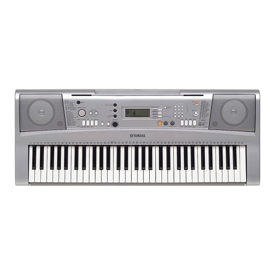
Yamaha PORTATONE PSR-E303 Manuale di servizio - Pagina 7
Sfoglia online o scarica il pdf Manuale di servizio per Strumento musicale Yamaha PORTATONE PSR-E303. Yamaha PORTATONE PSR-E303 36.

DISASSEMBLY PROCEDURE
Caution: Be sure to attach the removed filament tape just as it was before removal.
1.
Lower Case Assembly
(Time required: About 1 minute)
1-1
Remove the five (5) screws marked [240A], two (2)
screws marked [270A], and two (2) screws marked
[320]. The lower case assembly can then be
removed. (Fig. 1)
2.
DMLCD circuit board
(Time required: About 3 minutes)
2-1
Remove the lower case assembly. (See procedure 1)
2-2
Remove the eight (8) screws marked [240B]. The
DMLCD circuit board can then be removed. (Fig. 2)
Bottom view
[240A]
[320]
Top view
Speaker Grille L
Lower Case Assembly
[270A]
[240A]
Lower Case Keyboard Assembly
Knob (Master Volume)
[240]: Bind Head Tapping Screw-B 3.0X12 MFZN2Y (VE683000)
[270]: Bind Head Tapping Screw-B 3.0X30 MFZN2Y (V7213700)
[320]: Bind Head Tapping Screw-B 3.0X20 MFZN2Y (VI064600)
(Fig.1)
∗
When installing the DMLCD circuit board, tighten
the screws 1 through 8 in numerical order. (Fig. 2)
∗
If the DMLCD circuit board is replaced, execute the
"Factory Set" in the test program.
3.
LCD
(Time required: About 3 minutes)
3-1
Remove the lower case assembly. (See procedure 1)
3-2
Remove the DMLCD circuit board. (See procedure 2)
3-3
Remove the LCD holder and rubber connector.
3-4
Remove the back light assembly. (Fig. 4)
3-5
Remove the LCD. (Fig. 4)
∗
When attaching the rubber connector, set the
conductive part to face inside. (Fig. 4)
[270A]
Battery Lid Assembly
Speaker Grille R
PSR-E303/YPT-300
[240A]
[320]
7
