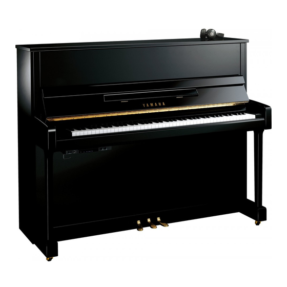
Yamaha SILENT Piano YM5SD Manuale di servizio - Pagina 6
Sfoglia online o scarica il pdf Manuale di servizio per Strumento musicale Yamaha SILENT Piano YM5SD. Yamaha SILENT Piano YM5SD 49.

SILENT SD SERIES
DISASSEMBLY PROCEDURE(分解手順)
A.
Switch Box Unit
1.
Removing the Switch Box Unit
(Time required: About 1 minute)
1-1
Remove the AC adaptor, connector assembly-KEY
and connector assembly-PDL from the backside of
the switch box unit.
1-2
Loosen the three (3) screws marked [41S], slide
the switch box unit toward you and then remove it
from the piano body, and carefully place it upside
down on a soft cloth. (Fig. A-1, Fig. A-2)
1-3
Remove the two (2) screws marked [A]. The
headphone hanger can then be removed from the
switch box unit. (Fig. A-2)
*
A label marked "KEY" or "PDL" is attached on
the connector assembly-KEY and connector
assembly-PDL respectively. Before connecting
a connector assembly to the switch box unit,
see the label to check if the connector assembly
is inserted to the correct connector, and then
insert all the way seated.
<Bottom view>
[41S]
[41S]
6
Switch box unit
(SW BOXユニット)
[41S]: Bind Head Screw (小ネジ+BIND) 4.0X12 MFZN2B3 (WF456600)
[A]: Bind Head Screw (小ネジ+BIND) 4.0X8 MFZN2B3 (WE969000)
A.
SW BOX ユニット
1.
SW BOX ユニットの取り外し
(所要時間: 約 1 分)
1-1
SW BOXユニットの背面からACアダプタ、 KEY束
線、PDL 束線を抜きます。
1-2
[41S]のネジ 3 本を緩めて、手前にスライドしてピ
アノ本体から SW BOX ユニットを外し、布を敷い
た上に上面を下にして静かに置きます。 (図 A-1、
図 A-2)
1-3
[A]のネジ 2 本を外して、SW BOX ユニットから
ヘッドホンハンガーを外します。 (図 A-2)
※
KEY 束線と PDL 束線にはそれぞれ KEY または
PDL と記されたラベルが貼られています。SW
BOX ユニットに束線を差し込む際は、ラベルに記
されたコネクタに、しっかりと奥まで差し込んで
ください。
Fig. A-1(図A-1)
Headphone hanger
(ヘッドホンハンガー)
(SW BOXユニット)
[A]
Fig. A-2(図A-2)
Switch box unit
