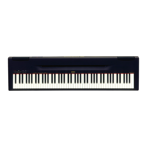
Yamaha P-60 Manuale di servizio - Pagina 9
Sfoglia online o scarica il pdf Manuale di servizio per Tastiera elettronica Yamaha P-60. Yamaha P-60 42. Yamaha p-60: quick start
Anche per Yamaha P-60: Manuale d'uso (40 pagine), Manuale di funzionamento rapido (2 pagine), Manuale d'uso (40 pagine)

speaker can then be removed. (Fig.6)
*
After reinstalling the speaker grille assembly, twist
the sections indicated by arrows to prevent it from
being removed easily. (Fig.8)
*
When removing the speakers, the speaker cushions
are removed together with them.
Make sure to install the speaker cushions when
reinstalling the speakers.
7.
Keyboard Asssembly (Time required: about
7 min)
7-1
Remove the upper case assembly. (See procedure 1.)
7-2
Remove the screw marked [150c] and the screw
marked [160a] to remove the DM holder assembly.
(Fig.3)
7-3
Remove the nine (9) screws marked [190] and the
two (2) screws marked [160b]. (Fig.3)
7-4
Slide the keyboard assembly backward, hold the
central area of it and raise it upright to remove.
(Fig.9)
*
It may twist and damage the frame to hold both
side ends of keyboard assembly or to carry it in a
horizantal state.
8.
Disassembling the GHD Keyboard
*
After inserting a round stick (Rod: TX000670)
between the frame and keys, remove the circuit
boards. (Fig.12)
8-1
Remove the keyboard assembly. (See Procedure 7)
(Fig. 8)
GH-D SW H
[260b]
(Fig. 10)
[260]: Bind Head Tapping Screw-P 3.0X10 MFZN2 (VT413400)
Keyboard Assembly
(Fig. 9)
8-2
GH-D_SW L circuit board.
Remove the seven (7) screws marked [260a]. The
GH-D_SW L circuit board can then be removed.
(Fig.10)
8-3
GH-D_SW H circuit board.
Remove the ten (10) screws marked [260b]. The
GH-D_SW H circuit board can then be removed.
(Fig.10)
GH-D SW L
[260b]
[260a]
P-60/P-60S
Keyboard Assembly
9
