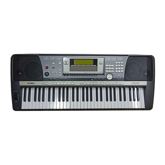
Yamaha PortaTone PSR-740 Manuale di servizio - Pagina 7
Sfoglia online o scarica il pdf Manuale di servizio per Tastiera elettronica Yamaha PortaTone PSR-740. Yamaha PortaTone PSR-740 18.
Anche per Yamaha PortaTone PSR-740: Procedure passo dopo passo (21 pagine)

YSS236-F (XT013A00) VOP3
PIN
NAME
I/O
NO.
1
VSS
Power supply
2
WA17
O
3
WA16
O
4
WA15
O
5
WA14
O
External memory address bus
6
WA13
O
7
WA12
O
8
WA11
O
9
WA10
O
10
VDD
Ground
11
VSS
Power supply
12
WA09
O
13
WA08
O
14
WA07
O
15
WA06
O
External memory address bus
16
WA05
O
17
WA04
O
18
WA03
O
19
WA02
O
20
VDD
Ground
21
VSS
Power supply
22
WA01
O
External memory address bus
23
O
WA00
24
WEN
O
External memory control (WEN)
25
OEN
O
External memory control (OEN)
26
RASN
O
External memory control (RASN)
27
CASN
O
External memory control (CASN)
28
CEN
O
External memory control (CEN)
29
VDD
Ground
30
VSS
Power supply
31
WD19
I/O
32
WD18
I/O
33
WD17
I/O
External memory data bus
34
WD16
I/O
35
WD15
I/O
36
WD14
I/O
37
VDD
Ground
38
VSS
Power supply
39
WD13
I/O
40
WD12
I/O
41
WD11
I/O
42
WD10
I/O
External memory data bus
43
WD09
I/O
44
I/O
WD08
45
WD07
I/O
46
VDD
Ground
47
VSS
Power supply
48
WD06
I/O
49
WD05
I/O
50
WD04
I/O
51
WD03
I/O
External memory data bus
52
WD02
I/O
53
WD01
I/O
54
WD00
I/O
55
VDD
Ground
56
VSS
Power supply
57
TST2
O
58
TST1
O
Test output
59
TST0
O
60
MS
I
Memory select
61
LRCLK
O
LR clock for ADC
62
SI7
I
Serial input
63
SI6
I
64
VDD
Ground
65
VSS
Power supply
66
SI5
I
67
SI4
I
68
SI3
I
Serial input
69
SI2
I
70
SI1
I
71
SI0
I
72
DB1
I
Output bit type select for DAC
73
DB0
I
74
VDD
Ground
75
VSS
Power supply
76
ODFM
I
Output mode select for DAC
77
OFS3
I
78
OFS2
I
Serial output format select
79
OFS1
I
80
OFS0
I
FUNCTION
PIN
NAME
I/O
NO.
81
SO7
O
82
SO6
O
Serial output
83
SO5
O
84
VDD
Ground
85
VSS
Power supply
86
SO4
O
87
SO3
O
88
SO2
O
Serial output
89
SO1
O
90
SO0
O
91
WDCK
O
Data enable for DAC
92
SWPKON
O
SWP00 format key on output
93
IRQN
O
EG interrupt
94
VDD
Ground
95
VSS
Power supply
96
XTAL_I
I
Quartz crystal terminal
97
XTAL_O
O
Quartz crystal terminal
98
MCLK
O
Oscillate clock output
99
VDD
Ground
100
VSS
Power supply
101
MICN
I
Initial clear
102
CLKIN
I
Master clock input
103
I
SYWIN
Sync.signal input
104
SYW
O
Sync.signal output
105
SYWD
O
Sync.signal output
106
VDD
Ground
107
VSS
Power supply
108
CLKO
O
For test (512 fs output)
109
WCLK
O
2 times sync.clock output (256 fs)
110
HCLK
O
4 times sync.clock output (128 fs)
111
QCLK
O
8 times sync.clock output (64 fs)
112
TSTCI
I
PLL test input
113
VDD
Ground
114
VSS
Power supply
115
(NC)
116
VDD(PLL)
117
CPO
O
PLL control output
118
CPIN
I
PLL control input
119
REF
I
PLL control intput
120
VSS(PLL)
121
(NC)
122
VDD
Ground
123
VSS
Power supply
124
TSTCS
I
PLL test input
125
CA6
I
126
CA5
I
CPU address bus
127
CA4
I
128
CA3
I
129
CA2
I
130
VDD
Ground
131
VSS
Power supply
132
CA1
I
CPU address bus
133
CA0
I
Lo/Hi select in 8 bits write
134
CSN
I
Chip select
135
RDN
I
Register read
136
WRN
I
Register write
137
BTYP
Data bus type select
138
VDD
Ground
139
VSS
Power supply
140
CD15
I/O
141
CD14
I/O
142
CD13
I/O
CPU data bus
143
CD12
I/O
144
CD11
I/O
145
VDD
Ground
146
VSS
Power supply
147
CD10
I/O
148
CD09
I/O
149
CD08
I/O
CPU data bus
150
CD07
I/O
151
CD06
I/O
152
CD05
I/O
153
VDD
Ground
154
VSS
Power supply
155
CD04
I/O
156
CD03
I/O
157
CD02
I/O
CPU data bus
158
CD01
I/O
159
CD00
I/O
160
VDD
Ground
PSR-740/PSR-640
FUNCTION
17
