Directed Xpresskit DBALL2 Manuale di installazione - Pagina 3

Sfoglia online o scarica il pdf Manuale di installazione per Per serrature Directed Xpresskit DBALL2. Directed Xpresskit DBALL2 15. Ford5 remote start ready (rsr) installation
Anche per Directed Xpresskit DBALL2: Manuale di installazione (12 pagine), Manuale di installazione (19 pagine), Manuale di installazione (18 pagine), Manuale (14 pagine), Manuale di installazione (13 pagine), Manuale di installazione (14 pagine), Manuale di installazione (19 pagine), Manuale di installazione (16 pagine), Manuale di installazione (20 pagine), Manuale di installazione e di consultazione rapida (16 pagine), Manuale di installazione (18 pagine), Manuale di installazione (16 pagine), Manuale di installazione (18 pagine), Manuale di installazione (16 pagine), Manuale (19 pagine)
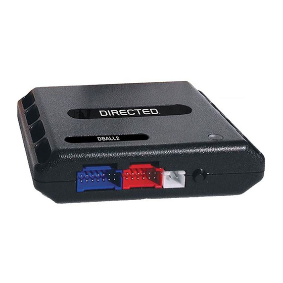
Directed Xpresskit DBALL2 Manuale di installazione
Platform: DBALL2
Firmware:
NISS06
Remote Start Ready
Installation Type 1
Important!
The
Hood Pin and Remote Start Safety Override Switch are mandatory safety
BCM Connector M19
(Black conn. at BCM)
40
20
39
19
38
18
37
17
36
16
15
35
(-) Unlock:
34
14
Pink,
pin 13
13
33
12
32
(-) Lock:
31
11
Brown,
pin 12
30
10
9
29
(-)
PTS
:
28
8
Yellow,
pin 9
27
7
26
6
25
5
24
4
23
3
22
2
21
1
( )
- Starter
:
Green, pin 19
12
11
10
9
8
7
6
5
4
3
2
1
24
23
22
21
20
19
18
17
16
15
14
13
BCM Connector E29
(Black conn, at BCM)
T
he vehicle MUST be disarmed for the power tailgate to operate
[ ] 1
If the module does not program, the HS CAN connections can be made at the BCM. See
[ ] 2
the installation guide for the 2017 Nissan Rogue (Smart Key).
With the exception of the
OBDII
(RSR)
( )
+ 12V
:
Green
or
Blue,
pin 1
1
White conn.
(back of dash fuse box)
BCM Connector M18 (Grey conn. at BCM)
20 19 18 17 16 15 14 13 12
39
38
37 36 35
34
33
32
40
Diode
s 3 x 1
HS CAN High:
[ ] 2
HS CAN Low:
[ ] 2
(-) Ground:
(-) Ignition Output:
(-) Ground:
(-)
Starter
Output:
(-) Ground:
(-) Unlock Output:
(-) Push-To-Start:
(-) Lock Output:
(-)
Hazards Output Red/Black:
( )
- Trunk Release
Output:
[1]
(-) P
ower Liftgate
:
[1]
Power Liftgate
(Green conn. at
Liftgate switch)
.
Diagno tic connector, all adapters are displayed from the wire side (unless specified otherwise).
s
Installation
devices, but
11
10 9
8
7
6
5
4
3
2
1
28
27
25
31
30 29
26
24 23 22 21
A
HS CAN High:
Blue, p
in 6
[ ] 2
1
8
9
16
HS CAN Low:
Pink, p
in 14
[ ] 2
Tan/Black:
3
Tan:
4
Brown:
7
Yellow:
8
Yellow/Red:
11
Brown/Red:
12
(+) 12V:
Red:
13
Black:
14
Black/White:
1
Green/Black:
2
Green/White:
3
:
4
Blue/Red:
12
RF
Lt. Green
, p
in
7
Prog Button
.
LED
You can connect to either a
RFTD
Refer to the SmartStart/
Installation Notes for more information.
Rev.: 20
are NOT
supplied with the
BCM
M19
B16
E29
M18
Diagnostic
connector
OBDII
Hood Pin
Remote Start Safety
Override Switch
6: White/Black: (-) Hood Input
DBALL
2
XL
202
OR
a SmartStart module.
XL
202
© 2017 Directed. All rights reserved.
1707
12
Page 3
DBALL
.