aerauliqa CTRL-XWS Manuale di istruzioni - Pagina 15
Sfoglia online o scarica il pdf Manuale di istruzioni per Controllore aerauliqa CTRL-XWS. aerauliqa CTRL-XWS 20.

4. 0-10V PROPORTIONAL FAN CONTROL AND ANEMOMETER BLOCK (Mode B)
4.1 WIRING DIAGRAM
1 = POWER SUPPLY 220Vac
2= POWER SUPPLY 220Vac
3= Pr2.... TEMPERATURE PROBE
4= GND-.. TEMPERATURE PROBE
5= Pr1.... ANEMOMETER
6= GND-.. ANEMOMETER
7= NO... NO CONTACT ALARM
8= C... COMMON ALARM
9= NC... NC CONTACT ALARM
18= GND-... - 0 FAN SIGNAL OUTPUT
19= +10... +10Vcc FAN SIGNAL OUTPUTLE
4.2 FUNCTIONALITIES
4.2.1 INDICATORS OF THE SYSTEM STATUS
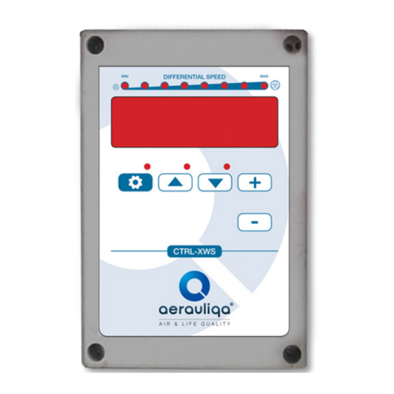
4.2.2 SETTING OF TEMPERATURE AND ANEMOMETER BLOCK
Press
(the led on the button flashes): the message SET.C = 10° is displayed - Setting of the temperature at which the fan starts.
-
+
Press
or
to increase / decrease.
(the led on the button flashes): the message SET = 3.0v is displayed - Setting of the anemometer block - Optional.
Press
+
-
Press
or
to increase / decrease.
Press
to exit (the led on the button switches off).
4.2.3 READING OF VENTILATION %
Press
or
: the ventilation % is displayed.
Release
or
: the temperature is shown on the display
DIFFERENTIAL SPEED
MIN
Ventilation speed indicator
15
0-10V FAN SIGNAL OUTPUT
MAX
