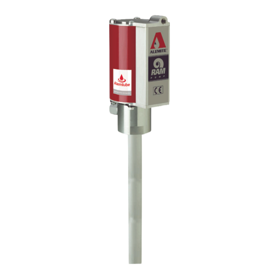
Alemite 9911-R1 Manuale di servizio per i proprietari - Pagina 3
Sfoglia online o scarica il pdf Manuale di servizio per i proprietari per Pompa dell'acqua Alemite 9911-R1. Alemite 9911-R1 16. High-pressure stripped pump
Anche per Alemite 9911-R1: Manuale di servizio (12 pagine), Manuale di servizio (12 pagine)

High pressure stripped pump preventative
maintenance schedule
Daily
Weekly
Wipe exterior with
Inspect for air and/or
clean cloth
mateiral leakage.
Performance curves
A pump's ability to deliver material is based
on the pressure (psi/bar) and quantity
(cfm/lpm) of air supplied to the motor and
the amount of material discharge [back]
pressure to be overcome within the system.
This chart contains curves based on three
different air pressures. The curves relate
delivery in pounds (kilograms) per minute
(X axis) to air consumption in cubic feet
(liters) per minute (right Y axis) and to mate-
rial discharge pressure in psi/Bars (left Y
axis).
Delivery versus discharge pressure and air consumption
Overhaul
Table 4
NOTE
Refer to Exploded views, pages 7 and 9 for
component identification on all overhaul
procedures.
Prior to performing any maintenance proce-
dure, the following safety precautions must
be observed. Personal injury may occur.
WARNING
Do not use halogenated hydrocarbon sol-
vents such as methylene chloride or
1,1,1-trichloroethane in this pump. An explo-
sion can result when aluminum and/or zinc-
plated parts in the pump come in contact
with halogenated hydrocarbon solvents.
Release all pressure within the system
prior to performing any overhaul procedure.
• Disconnect the air supply line from the
pump motor.
• Into an appropriate container, operate the
control valve to discharge remaining pres-
sure within the system.
Never point a control valve at any portion of
your body or another person. Accidental dis-
charge of pressure and/or material can result
in injury.
Read each step of the instructions care-
fully. Make sure a proper understanding is
achieved before proceeding.
Disassembly
Separate air motor from pump tube
1 Clamp the pump assembly in a soft-jaw
2 Remove cover (1a) by prying and
3 Remove screw (1b) from the top cap.
4 Remove nuts (1d) that secure the body
5 Remove bolts (1c) from the top cap.
6 Remove keepers (11) from the body.
7 Remove the top cap from the cylinder.
NOTE
Remove the Cylinder with care. Damage to
Quad-Ring (5) and/or O-Ring (8) can occur.
8 With a side-to-side motion, pull the
9 Remove o-ring (8) from the body.
10 Remove the bottom cap from the body.
Fig. 1
3
vise at body (10).
swinging the cover sideways away from
the cylinder. Refer to ser 339413 for
details.
to air motor assembly (1).
cylinder from the body and air piston (4).
