Alemite 9968-A Manuale di servizio - Pagina 9
Sfoglia online o scarica il pdf Manuale di servizio per Pompa dell'acqua Alemite 9968-A. Alemite 9968-A 11. Low-pressure stub pump
Anche per Alemite 9968-A: Manuale di servizio (16 pagine)
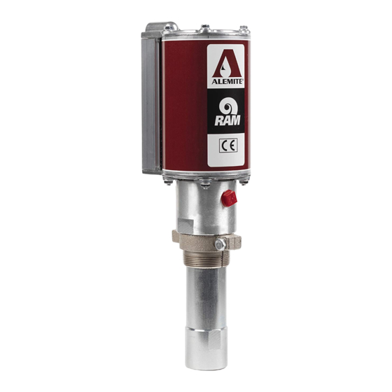
Low-Pressure Stub Pump
Attach Air Motor to Pump Tube
23. Clamp the pump assembly in a soft-jaw vise at Bung
Adapter (22) or Body (8).
24. Install the Bottom Cap onto the Body.
25. Install O-Ring (7) onto the upper groove of the Body.
CAUTION
Install the Cylinder with care. Damage to Quad-
Ring (6) and/or O-Ring (7) can occur.
HINT: Angle the Cylinder onto the Quad-
Ring.
26. Install the Cylinder over the Body's O-Ring and seat it
properly onto the Bottom Cap.
27. Install the Top Cap onto the Cylinder.
• Use care passing the O-Ring.
28. Install Keeper (9) into the groove of the Body.
• Make sure the hole aligns with Carriage Bolt (1c).
29. Install one Carriage Bolt through the Air Motor and
through the Keeper.
30. Install Flange Nut (1d).
• Do not tighten the Flange Nut at this time.
31. Repeat procedural steps 27 - 29 for the additional
Keepers and Carriage Bolts.
CAUTION
Do not overtighten Flange Nuts (1d). Component
damage can occur.
32. Torque each Flange Nut in an alternate pattern from 60
to 70 inch-pounds (6.8 - 7.9 Nm).
33. Install Screw (1b) into the Top Cap.
• Tighten the Screw to 50 inch-pounds (5.6 Nm).
34. "Snap" Cover (1a) onto the Cylinder.
Bench Test and Operation
1. Slowly supply air pressure [recommended minimum of
25 psi (1.7 Bars)] to the pump's motor.
• The pump assembly should cycle.
If the pump assembly does not cycle, refer to the
Troubleshooting Chart for details.
Alemite, LLC
With air pressure at zero:
2. Connect a product hose to the pump's fluid outlet.
• Direct the hose into an appropriate collection
container.
3. Place the pump in oil.
4. Slowly supply air pressure to the pump's motor.
5. Allow the pump to cycle slowly until the oil is free of
air.
If the pump assembly does not prime, refer to the
Troubleshooting Chart for details.
WARNING
Should leakage occur anywhere within the
system, disconnect air to the motor. Personal
injury can occur.
With air pressure at zero:
6. Attach a control valve to the outlet hose of the pump.
• Make sure the nozzle on the control valve is open.
7. Slowly supply air pressure to the pump's motor.
8. Allow the pump to cycle slowly until the oil is once
again free of air.
9. Set the air pressure to the normal operating pressure.
10. Operate the control valve into a container.
11. Shut off the control valve.
• Visually inspect the pump for external leaks.
• The pump should not cycle more than once or twice
in one hour.
If the pump does not stall, refer to the Troubleshooting
Chart for details.
12. Check the motor for air leakage.
If the motor leaks, refer to the Air Motor Service
Guide for details.
Installation
Additional items that should be incorporated into the
air piping systems are listed in Table 4.
Part Number
5604-2
Moisture Separator
7604-B
Regulator and Gauge
Table 4 Air Line Components
9
SER 9968
Description
Revision (8-10)