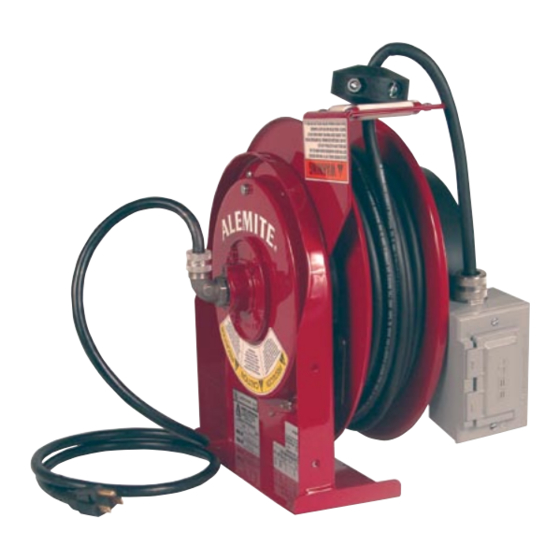
Alemite 7260 Manuale di servizio - Pagina 4
Sfoglia online o scarica il pdf Manuale di servizio per Strumenti Alemite 7260. Alemite 7260 5. Cord reel with duplex outlet

SER 7260
See Fig. 3
1.
Ensure that tool or fixture connected to the duplex outlet
is in good working order. If it is, proceed to step 2.
2.
Remove power from reel.
3.
Remove access cover (1).
4.
Reapply power to reel.
5.
Check for correct voltage (120 vac) at terminal strip (2).
If voltage reading is correct, replace output electrical
cord (refer to SERVICE INSTRUCTIONS). If voltage
reading is incorrect, proceed to step 6.
6.
Remove power from reel.
7.
Using an ohmmeter, check continuity of input electri-
cal cord. If cord checks good, replace cord reel. If cord
is faulty, replace cord (refer to SERVICE INSTRUC-
TIONS).
8.
Replace access cover (1).
SERVICE INSTRUCTIONS
Maintain reel by following the service instructions given
below. Refer all other repairs, other than those listed, only to
an authorized service person or directly to Reelcraft. Failure
to do so can result in personal injury and/or equipment dam-
age and may void the warranty.
(Refer to page 5 when referencing parts).
WARNING:
Remove power from reel before performing any of
the following procedures.
REPLACING THE OUTPUT ELECTRICAL
CORD
WARNING:
Use extreme caution, reel under tension. Avoid
releasing latch mechanism.
Use only 12/3 cable.
See Fig. 4
1.
Pull output electrical cord from reel until fully extended,
then latch.
2.
Remove output electrical cord bumper (1).
3.
Disconnect output electrical cord (5) at terminal strip
(4).
4.
Remove strain relief (2). Remove output electrical cord.
5.
Install replacement electrical cord by reversing steps 2
through 4.
6.
Release latch and rewind electrical cord on reel.
7.
Replace access cover (8).
Alemite, LLC
REPLACING THE INPUT ELECTRICAL
CORD
See Fig. 4
WARNING:
Use only 12/3 cable.
1. Remove wire nuts (7) securing input electrical cord to
collector assembly (6).
2. Remove 90 degree elbow (3).
3. Remove input electrical cord.
4. Remove 11" (279 mm) of outer jacket from replacement
input electrical cord (input electrical cord wires must
protrude a minimum of 6" (152 mm) from center of col-
lector assembly).
5. Install replacement input electrical cord by reversing
steps 1 through 3.
6. Replace access cover (8).
8
7
Fig. 4
4
1
2
3
4
5
6
Revision (2-05)
