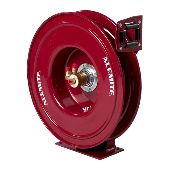
Alemite 7338-C Manuale di servizio - Pagina 8
Sfoglia online o scarica il pdf Manuale di servizio per Strumenti Alemite 7338-C. Alemite 7338-C 12. Severe-duty welding hose reel

SER 7338-C
17. Install and hold Woodruff Key (43) into the slot of the
Assembly.
18. Slide Spring Arbor (44) [flat side first] onto the shaft
and onto the Woodruff Key.
19. Install remaining O-Ring (41) into the groove of the
Shaft and Flange Assembly.
Sheave and Power Spring Assembly
20. Position Sheave Assembly (16) Bearing side up.
21. Install Gasket (25) onto the Sheave Assembly.
• Make sure to align the notch in the Gasket with the
alignment mark on the Sheave Assembly.
See Figure 2.
22. Position Power Spring Assembly (26) onto the Sheave
Assembly.
• Make sure to align the mark on the Power Spring
with the notch in the Gasket. See Figure 2.
23. Secure the Power Spring Assembly to the Sheave
Assembly using screws and nuts included with
Replacement Assembly.
• Make sure the Gasket does not move.
• Make sure the screw heads seat properly into the rib
of the sheave.
24. Install O-Ring (27) into the groove of the Power
Spring Assembly.
25. Install and seat the Power Spring and Sheave
Assembly onto the Spring Arbor and Bearing.
• Use care not to damage the O-Rings.
• Make sure the end of the power spring properly
engages the cam on the Spring Arbor.
• Make sure the ratchet either clears the Pawl or
engages properly.
26. Install Washer (12) and Retaining Ring (11) onto the
Shaft and Flange Assembly.
Swivel Assembly
WARNING
Use a thread sealant that contains no
petroleum-based materials.
Teflon tape is recommended.
Personal injury can occur due to explosion.
Revision (12-07)
Severe-Duty Welding Hose Reel
27. Screw Hose Connector (6 and 7) [with Teflon tape]
into each Street Elbow (5) as required.
• Tighten each Connector securely.
28. Screw each Street Elbow assembly [with Teflon tape]
into Swivel Body (8) as required.
• Tighten each Elbow securely.
• Make sure the Elbow orients properly.
29. Install and position each O-Ring (3) into the deeper
grooves on Swivel Shaft (1).
• Use care during the installation process.
HINT: Position the first O-Ring in the first
groove. "Leap-frog" each additional O-Ring
over the previous one(s).
30. Install Bearing (2) onto the far end of the Swivel Shaft.
31. Install Bearing (4) onto the center of the Shaft.
IMPORTANT: Swivel Body must assemble
onto the Bearings without interference. Any
interference indicates a Bearing is not seated
in its groove.
32. Install the acetylene Swivel Body Assembly (with
notches in Connector) onto the Shaft.
• Make sure not to damage the O-Rings or the
Bearings.
• Make sure to orient the Connector properly.
HINT: Hold each Bearing firmly on the
Shaft when installing the Swivel Body.
33. Install additional Bearing (2) onto the Swivel Shaft.
IMPORTANT: Swivel Body must assemble
onto the Bearings without interference. Any
interference indicates a Bearing is not seated
in its groove.
34. Install the oxygen Swivel Body Assembly onto the
Shaft.
• Use care not to damage the O-Rings or the Bearings.
• Make sure to orient the Connector properly.
35. Install Washer (9) and Retaining Ring (10) onto the
Swivel Shaft.
36. Screw the Swivel assembly (with Teflon tape] into the
Shaft and Flange Assembly.
• Tighten the connection from 23 to 31 ft-lbs
(31 - 42 Nm).
8
Alemite Corporation
