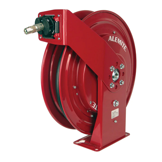
Alemite 7346 Manuale di servizio - Pagina 4
Sfoglia online o scarica il pdf Manuale di servizio per Cavi e connettori Alemite 7346. Alemite 7346 4. High-capacity reel

SER 7345
WARNING
Release all pressure within the system prior to
performing any overhaul procedure. Personal injury can
occur.
Do not attempt to disassemble the Power Spring Assem-
bly. Personal injury can occur.
Read each step of the instructions carefully. Make sure a
proper understanding is achieved before proceeding.
Installation
CAUTION
The base of the reel must be at a height no greater than
16 feet (4.9 m) from the floor to comply with the warranty.
Inlet Connection
CAUTION
Never connect rigid piping to the Swivel assembly. Dam-
age to components can occur.
Threaded
1. Screw a connecting hose (with thread sealant) into Inlet
Adaptor (23).
2. Attach the connecting hose to the supply line.
Victaulic
NOTE: Victaulic - Type swivel joint inlet connec-
tions must be carefully aligned. Two victaulic con-
nections, correctly installed, allow adequate
flexibility for smooth rotation.
1. Attach victaulic coupling to Inlet Adaptor (23) and supply
line.
2. Adjust supply line to verify flexibility exists for proper
alignment.
NOTE: Failure to use flexible connector with any
live reel will void warranty.
3. Lubricate Ring Seal (24) with NLGI2 lithium grease.
4. Insert Ring Seal into Inlet Adaptor.
5. Attach Inlet Adaptor to Bearing Housing Assembly (20) using
three Screws (22).
Delivery Hose
6. Feed the inlet end of delivery hose through the guide
assembly.
7. Connect the delivery hose (with thread sealant) to the outlet
riser.
HINT: Orient the hose to allow its natural curve to
match the Sheave.
Revision (10-12)
Figure 3 Victaulic Connection
This reduces torque load on the Power Spring
Assembly and eliminates the tendency of the
hose to stack on one side of the Sheave.
8. Rotate the Sheave Assembly (10) to coil the delivery hose
onto it.
9. Install a control valve onto the delivery hose.
10. Pressurize the system.
• Check for leaks.
11. Install and secure the Hose Stop (46) to the delivery hose at
the desired position.
Spring Tension
12. Check to ensure the tension on the power spring is
sufficient to properly hold the hose stop against the hose
guide.
Should the power spring tension require adjustment:
CAUTION
Do not overwind the power spring. Too much tension
reduces the life of the spring.
When the hose is fully extended from the reel, the
power spring should be a minimum of 1/2 turn from a
fully wound condition.
13. Release all pressure within the system.
14. Remove the control valve and the hose stop from the
delivery hose.
15. Pull the free end of the delivery hose through the guide.
16. Rotate the Sheave Assembly in the required direction.
17. Install the control valve and the hose stop.
18. Pressurize the system.
19. Check to ensure the tension on the power spring is
sufficient to properly hold the hose stop against the hose
guide.
20. Repeat steps 13 - 20 until the proper tension is achieved.
4
High-Capacity Reel
Alemite LLC
