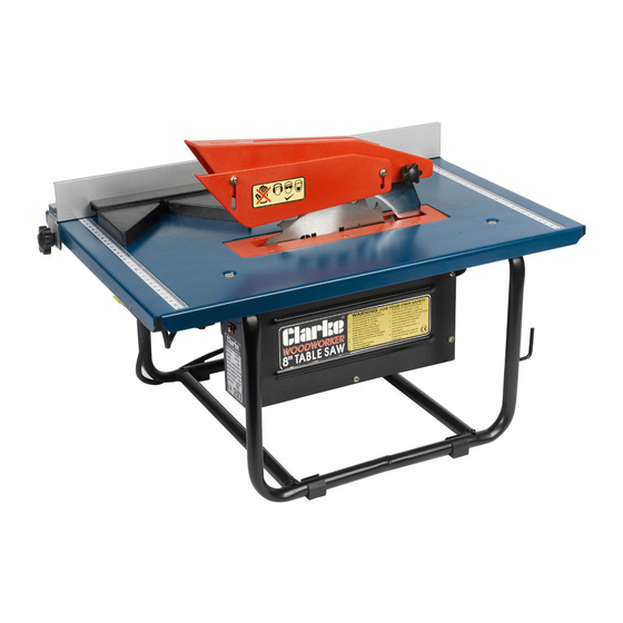
Clarke WOODWORKER CTS800B Istruzioni per il funzionamento e la manutenzione - Pagina 8
Sfoglia online o scarica il pdf Istruzioni per il funzionamento e la manutenzione per Sega Clarke WOODWORKER CTS800B. Clarke WOODWORKER CTS800B 15. 8” 200mm table saw

MOUNTING THE SAW
If the Saw is to be bolted to a workbench, you should ensure that it is positioned in
the most convenient location. Ensure adequate lighting is available and the
electrical supply is close at hand.
A mounting board should be used if a permanent mounting is unavailable or not
desired. The board is necessary in order to give the saw stability during operation.
It is recommended that the board dimensions are not less that 450x600mm and at
least 15mm thick.
Once mounted, as described below, the board must be securely clamped to a
workbench, using at least two 'G' clamps, one at each side, and a constant check
made to ensure they are tight during operation.
To mount the saw, drill four 8mm holes, using
the machine as a template to mark out the
position of the holes, and bolt the machine
down with 5mm bolts, ensuring flat washers are
used between the bolt head and base.
If a mounting board is used, countersunk head
screws should be used, with the holes in the
underside of the board countersunk to suit. The
mounting holes should be centrally located on
the board.
It is important to ensure the nuts are not over-
tightened, and are tightened progressively to
avoid distorting the base.
RIP FENCE
Your Table Saw is provided with a Rip Fence
which is essential to ensure straight line cutting,
and should ALWAYS be used when rip sawing.
The Fence is secured to the table with two
knob head screws, acting on a pair of
clamp plates, one at the front and one
at the rear of the table.
The fence may be placed at any suitable
position on the table, and either left
or right of the saw blade. Do not
over-tighten the securing knobs.
Measurement scales are provided
at the front and back of the table. These
may be used to position the rip fence for
rough cutting. If precision is required, use a
ruler between the rip fence and the front
and back of the blade.
Rip Fence is shown in its Lower Position
8
Fig.2
Fig.3
