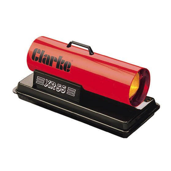
Clarke XR55 Istruzioni per il funzionamento e la manutenzione - Pagina 7
Sfoglia online o scarica il pdf Istruzioni per il funzionamento e la manutenzione per Riscaldatore Clarke XR55. Clarke XR55 20. Paraffin/diesel heaters

1. The Fuel System.
Fuel is held in the tank at the base of the system, at atmospheric pressure. An air pump,
mounted on the end of the motor, draws air through a filter, compresses it, and forces it
through a second filter, and via an air line, directly to the burner head nozzle. The speed of
the air over the nozzle, causes a depression. Fuel is therefore forced up the tube by
atmospheric pressure, through a filter, and out of the nozzle in the form of a spray.
It is important to ensure that the vent in the filler cap is not blocked at any time, otherwise
fuel will not reach the nozzle.
This heater is capable of burning
Paraffin or Diesel oil. NEVER use petrol.
As these fuels burn at different
rates, provision is made to ensure
that the correct volume of air is
allowed
into
chamber for each type of fuel.
This is achieved by means of a
blanking plate, at the rear of the
burner, shown in Fig. 3,
The blanking plate is factory set to burn PARAFFIN, so that tab'A' covers vent 'B'
TO BURN DIESEL, THE BLANKING PLATE MUST BE MOVED TO THE POSITION SHOWN IN
FIG.3, OTHERWISE DAMAGE TO THE COMBUSTION CHAMBER WILL OCCUR
NOTE:
A. In the case of MODEL XR75, there is insufficient room to store the blanking plate in the position
shown above. The plate should therefore be removed and retained for possible future use.
B. In the case of Model XR55, no changes are required for the burning of Diesel oil.
2. The Air System.
Additional air is supplied to the combustion chamber by a fan, which is mounted on
the opposite end of the motor shaft to the Air Pump. Openings around the burner
head allow a portion of this air to be drawn into the combustion chamber, where it
mixes with the air and fuel from the nozzle, and ensures that all the fuel is burned,
preventing the emission of black smoke.
The remaining air is directed around and over the combustion chamber, until it finally mixes
with the heated air from the combustion chamber, and is ejected as a jet of clean hot air.
3. The Ignition System.
A constant arc is struck between the electrodes, which ignites the air and fuel
mixture. It is important that the electrode gap is correctly maintained, otherwise
arcing will not take place...see Maintenance.
4. The Safety Control System.
A light sensitive photo cell (flame sensor) trips the motor if the flame goes out for
any reason, causing the heater to shut down.
the
combustion
WARNING!
7
Fig. 3
