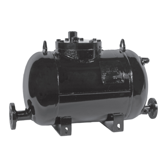
Armstrong Double Duty 6 Manuale di installazione e manutenzione
Sfoglia online o scarica il pdf Manuale di installazione e manutenzione per Pompa dell'acqua Armstrong Double Duty 6. Armstrong Double Duty 6 6. Steam trap/pump combination

This bulletin should be used by experienced personnel as a guide to the installation and maintenance of the Armstrong DD6 or DD6 package.
Selection or installation of equipment should always be accompanied by competent technical assistance. We encourage you to contact Armstrong
or its local representative if further information is required.
Application
When there is modulating control on heat exchange equipment there is a possibility that the system will stall (no
longer be able to drain condensate). If only a steam trap is used condensate could flood the heat exchange
equipment causing corrosion, water hammer, and poor temperature control. The Double Duty™ has a steam trap
with an integral pump to prevent the system from stalling. If the condensate floods the body of the Double Duty™
and reaches its upper trip point high pressure steam will enter the body and push the condensate out. This prevents
condensate from accumulating in the heat exchange equipment.
Suggested Accessories
• Inlet and discharge check valves
• Gauge glass assembly for pump
• Gauge glass assembly for receiver
• Pressure gauge assembly pump body
• Pressure gauge assembly receiver
• Pressure gauge assembly motive steam
• Pressure gauge assembly discharge piping
• Pressure gauge assembly heat exchange equipment
• Receiver
Double Duty™ 6 Physical Data
"A"
"B"
"C"
"D"
"E"
"F"
"G"
"H"
"J"
"K"
"L"
"M"
"N"
"O"
Weight lb (kg)
E
G
H
A
Armstrong Double Duty™ 6
Steam Trap/Pump Combination
Installation and Maintenance
in
mm
29
737
16-11/16
424
1-1/2
38
1
25
7/8
22
1-1/8
48
2-1/4
57
24
610
14
356
10-13/16
275
10
254
2-13/16
71
8
203
3-3/16
81
140 (64)
K
J
C
1-1/2" 150#
Flange Inlet
Double Duty™ 6 Specifications
Model
Motive Fluid
Maximum Operating Pressure
Minimum Motive Differential
Maximum Operating Temperature
Body
Mechanism
Float
Connections (condensate)
Inlet Check Valve
Discharge Check Valve
Springs
1" 150#
D
Flange Outlet
L
M
1/2" NPT
Drain
IB-119
DD6
Steam
200 psi
10 psi
400°F
Carbon Steel
Stainless Steel
Stainless Steel
150# Flange
Optional 1-1/2"
Optional 1"
Inconel X-750
1/2" NPT
Motive
1" NPT
Vent
B
O
N
.56 x 1.06
Slot (4 Places)
