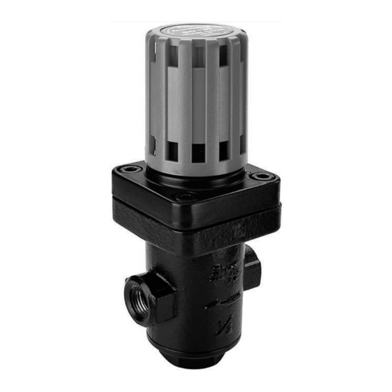
Armstrong GD-30S Istruzioni - Pagina 2
Sfoglia online o scarica il pdf Istruzioni per Unità di controllo Armstrong GD-30S. Armstrong GD-30S 4. Bronze or stainless steel direct acting pressure reducing valve for steam, air and non-corrosive gases
Anche per Armstrong GD-30S: Manuale di avvio rapido (2 pagine)

INSTALLATION - INSTALLATIONSANWEISUNG - INSTALLATION
INSTALACION - INSTALLATIE - INSTALLAZIONE
Model shown on the drawing: MSD-08 & MSD-12 – Die Zeichnung zeigt das Modell MSD-08 & MSD-12 –
Schéma : MSD-08 & MSD-12 - Modelo del dibujo: MSD-08 & MSD-12 –
Getoond model op tekening: MSD-08 & MSD-12 – Modello in figura: MSD-08 & MSD-12
Not included
Nicht enthalten
Non compris
No includo
Niet meegeleverd
Non inclusi
START-UP, ADJUSTMENT AND SHUT-DOWN PROCEDURE
INBETRIEBNAHME, EINSTELLUNG UND AUSSERBETRIEBNAHME
PUESTA EN MARCHA, AJUSTE Y CIERRE
PROCEDURE VOOR HET OPSTARTEN, AFSTELLEN EN UITSCHAKELEN
PROCEDURE DI AVVIO, REGOLAZIONE E FERMATA
For detailed hookups and adapted start-up and shut-down
procedures, see Armstrong literature or consult your local
Representative.
Downstream demand is necessary to set the pressure reducing valve.
The installation shown below is for steam applications. For air or other
gases, the steam trap (6) should be replaced by a liquid drainer.
- Close the isolation valves (3 & 4) and open the by-pass valve (2) to
blow-down inlet piping. After having blown the system down, close the
by-pass valve (2);
- Make sure steam trap (6) is operating properly;
- Completely open the inlet valve (3) and partially open the outlet valve
(4);
- Push down the adjusting handle of the Pressure Reducing Valve
(1) and turn it clockwise until the desired pressure is reached at the
outlet of the Pressure Reducing Valve (1). Release handle, which will
automatically lock;
- Completely open the outlet valve (4), pressure reducing station should
now operate normally;
- To shut the system down, close the inlet valve (3) first, then
the outlet valve (4).
Voor gedetailleerde montage en installatie instructies zie het
betreffende Armstrong documentatieblad of neem contact op met uw
plaatselijke vertegenwoordiger.
Een afname verderop in de installatie is nodig voor het instellen van het
drukreduceertoestel.
Onderstaande installatie is bedoeld voor stoomtoepassingen. Voor
lucht of andere gassen dient de condenspot (6) te worden vervangen
door een vloeistoflozer.
- Sluit de isolatiekleppen (3 & 4) en open de bypassklep (2) om de
inlaatleiding af te blazen. Als het systeem is afgeblazen, sluit u de
bypassklep (2);
- Controleer of de condenspot (6) correct functioneert;
- Zet de inlaatklep (3) helemaal en de uitlaatklep (4) een stukje open;
- Druk de kap van het toestel (1) omlaag en draai deze rechtsom tot de
betreffende druk is bereikt aan de uitlaat van de drukreduceerklep (1).
Laat de hefboom los. Deze vergrendelt automatisch;
- Zet de uitlaatklep (4) volledig open. Het drukreduceerstation moet nu
normaal functioneren;
- Sluit eerst de inlaatklep (3) en daarna de uitlaatklep (4) om
het systeem uit te schakelen.
PRV connection
Druckminderventil-Anschluss
Raccord du détendeur
Conexión PRV
PRV aansluiting
Connessioni VRP
MISE EN SERVICE, RÉGLAGE ET ARRÊT
Para conocer las posibilidades de conexión y procedimientos de
parada y puesta en marcha, consulte los catálogos Armstrong o
hable con su Representante local.
Es necesario que haya demanda de flujo hacia abajo para poder
configurar la válvula de reducción de presión.
La instalación que se muestra a continuación es para aplicaciones
de vapor. Para aire y otros gases, el purgador de vapor (6) tiene que
reemplazarse por un drenador de líquido.
- Cierre las válvulas de aislamiento (3 y 4) y abra la válvula de desvío
(2) para que el aire circule por las tuberías. Después de hacer circular
el aire, cierre la válvula de desvío (2);
- Asegúrese de que el purgador de vapor (6) está funcionando
correctamente;
- Abra al completo la válvula de entrada (3) y abra
parcialmente la válvula de salida (4);
Detaillierte Informationen über Einbau, Inbetriebnahme und
Außerbetriebnahme finden Sie in den ARMSTRONG Datenblättern,
oder Sie fragen Ihre ARMSTRONG Vertretung.
Zur Einstellung des Druckminderventils ist eine
Auslassdruckanforderung erforderlich.
Die unten abgebildete Installation bezieht sich auf Dampfanwendungen.
Für Luft oder andere Gase sollte der Kondensatableiter (6) durch einen
Entwässerer ausgetauscht werden.
- Absperrventile (3 & 4) schließen und Bypass-Ventil (2) öffnen, um das
Einlassrohr zu durchzublasen. Nach dem Durchblasen des Systems das
Bypass-Ventil (2) schließen;
- Ordnungsgemäße Funktion des Kondensatableiters (6) sicherstellen;
- Einlassventil (3) vollständig und Auslassventil (4) teilweise öffnen;
- Einstellhebel des Druckminderventils (1) herunterdrücken und
im Uhrzeigersinn drehen, bis der gewünschte Druck am Auslass
des Druckminderventils (1) erreicht ist. Hebel loslassen, er rastet
automatisch ein;
- Auslassventil (4) vollständig öffnen. Die Druckminderanlage sollte nun
normal funktionieren;
- Für die Außerbetriebnahme zuerst das Einlassventil (3) und
dann das Auslassventil (4) schließen.
