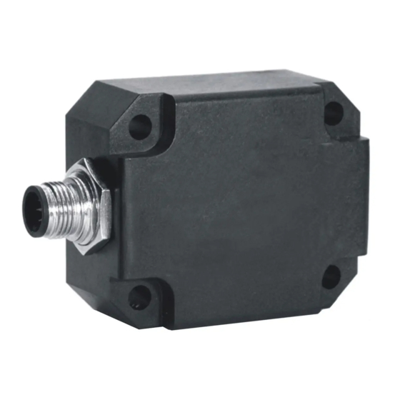
DIS Sensors CAN Manuale d'uso - Pagina 6
Sfoglia online o scarica il pdf Manuale d'uso per Accessories DIS Sensors CAN. DIS Sensors CAN 18. Inclination safety sensor

CAN User Manual
Inclination Safety Sensor
(Type D) V2.0
8
Signal processing
The Safety sensor transmits SRDO messages. These message must be used to check the data and timing. In this
SRDO message the angle information is available in normal and in inverse format. Customer should compare
these messages in order to check the sensor output is safe. It is also possible to send the data via the TPDO
message according to CiA410 but in this case the sensor should be treated as a non-safety sensor. An output
filter is available for a stable signal. To compensate for mounting tolerances a pre-set/zero adjustment option is
available. When pre-set/zero values are changed a CRC must be calculated off-line (CRC calculate tool available)
and written to the sensor. The settings of the SRDO messages are also protected with a CRC code. When these
are changed also new CRC code must be determined. When the sensor detects a failure an emergency message
is generated and a safe state is activated. In the safe state no communication is possible (No SRDO, TPDO and
Heartbeat).
8.1 Sample rate:
The internal g-sensor chip is sampled every 10ms. Each sample of the element consists of 16 samples for each
axis. Resulting in sample rate of 1600 Hz. These samples are input for a 32 tabs FIR input low pass filter. Each
10ms new data is available for the CAN bus.
8.2 Averaging:
The FIR filtered values are averaged during the TPDO1 cycle time set by the customer. A longer TPDO cycle time
results is a smaller bandwidth and therefore a more stable output signal (less noise), but also more phase delay.
e.g. if Event time TPDO1 is 10 ms (fastest time) à a filtered value of 16 samples is available.
e.g. if Event time TPDO1 is 100 ms à an average value of 10*16 samples is available.
8.3 Output filter:
The output of the sensor can be extra filtered by a 1
Via the CAN object dictionary (index 300Eh) this filter can be controlled, by setting the time-constant in ms, with
a maximum of the redundancy compare time (set by index 4006h sub-index 02h) .
The time constant is defined as the time in which the output changes to 70% of the step after a step response.
The -3dB frequency can be calculated by the formula f = 1 / (2*pi*time-constant). This -3dB frequency is
independent of a change in TPDO1 event time and the SRDO refresh time. But when the output filter time-
constant is set < min. [TPDO1 event time, the SRDO refresh time], the output filter is disabled. With the factory
default, the filter time-constant can be set within 50ms – 2000ms, other value will disable the filter.
st
order low-pass filter. Default this output filter is disabled.
Page 6 of 18
