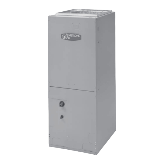
Armstrong Air BCS2 Series Manuale di istruzioni per l'installazione - Pagina 6
Sfoglia online o scarica il pdf Manuale di istruzioni per l'installazione per Manipolatori d'aria Armstrong Air BCS2 Series. Armstrong Air BCS2 Series 15.

NOTE
: Use copper conductors only.
All field wiring must be done in accordance with National
•
Electrical Code, applicable requirements of UL and local
codes, where applicable.
•
Electrical wiring, disconnect means and over-current
protection are to be supplied by the installer. Refer to
the air handler rating plate for maximum over-current
protection, minimum circuit ampacity, as well as
operating voltage.
The power supply must be sized and protected
•
according to the specifications supplied on the product.
This air handler is factory-configured for 240 volt, single
•
phase, 60 cycles. For 208-volt applications, see "208
Volt Conversion" in the "Make Electrical Connections"
section.
For optional electric heater applications, see
•
"Accessories." Refer to the instructions provided with
the instructions provided with the accessory for proper
installation (Models without Factory-installed electric
heat only).
Ductwork Requirements
•
Install the conditioned air plenum, ducts and air filters
(not provided) in accordance with NFPA 90B Standard
for the installation of Warm Air Heating and Air-
Conditioning Systems (latest edition).
The air handler is provided with flanges for the
•
connection of the plenum and ducts.
The air handler is equipped with flanges that can form a
•
filter rack for the installation of the air filter, or the filter
may be installed as part of the return air duct system.
Air filters must be listed as Class 2 furnace air filters.
•
Supply and return ductwork must be adequately sized to
•
meet the system's air requirements and static pressure
capabilities. Ductwork should be insulated with a
minimum of 1" thick insulation with a vapor barrier in
conditioned areas or 2" minimum in unconditioned
areas.
Supply plenum should be the same size as the flanged
•
opening provided around the blower outlet and should
extend ideally at least 3 ft. from the air handler before
turning or branching off plenum into duct runs. The
plenum forms an extension of the blower housing and
minimizes air expansion losses from the blower.
INSTALLATION INSTRUCTIONS
Inspect Shipment
!
W
!
W
!
W
Excessive Weight Hazard
Use two or more people to move and install air
handler. Failure to do so can result in back or
other injury.
A
R
N
I
N
G
A
R
N
I
N
G
A
R
N
I
N
G
These air handlers are completely factory assembled, and all
components are performance tested. Each unit consists of a
blower assembly, refrigerant coil, and controls, in an insulated
galvanized steel factory finished enclosure. Knockouts are
provided for electrical wiring entrance.
1.
Check the unit rating plate to confirm specifications
are as ordered.
2.
Upon receipt of equipment, thoroughly inspect it for
possible shipping damage. Closely examine the
unit inside the carton if the carton is damaged.
3.
If damage is found, it should be noted on the
carrier's freight bill. Damage claims should be filed
with carrier immediately. Claims of shortages
should be filed with the seller within 5 days.
NOTE:
If any damages are discovered and reported to the
carrier, do not install the unit because your claim may be denied.
If a filter is to be installed at the air handler, a filter rack must be
formed using factory-supplied flanges.
1.
Lay air handler on its back
2.
Pry filter rack tabs out.
6
