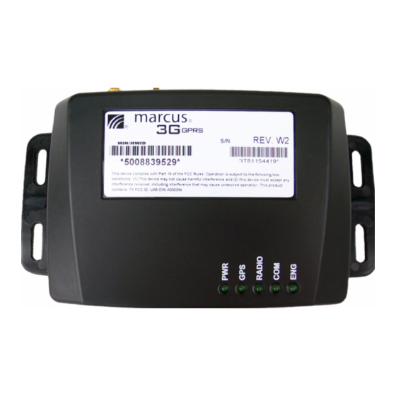
Discrete Wireless MARCUS 3G GPRS Manuale di installazione - Pagina 10
Sfoglia online o scarica il pdf Manuale di installazione per Unità di controllo Discrete Wireless MARCUS 3G GPRS. Discrete Wireless MARCUS 3G GPRS 20. Radio module

4.3 Securing ground wire.
Strip enough slack in the power cable to
allow sufficient length as to attach the
black wire to a solid metal surface that is
welded, not bolted to an under dash
support. Add a grounding ring connector
to the end of the black wire, crimp it and
screw it securely onto a non painted metal
frame or plate.
Temporarily connect the
radio module to ensure it is on constant
power before final placement.
4.3.1 Picture - Proper placement of
electrical ground wire
NOTE:
When installing the Marcus® 3G unit in any late (new) model vehicle, verify all
connections using a digital multi-meter. In some instances, obtaining power will require direct
connection to the battery. CAN based vehicles will contain data lines which will show voltage on
the line itself (usually 5V) but the line is actually a data line. Most late (new) model vehicles
utilize "CAN" based ignition and accessory circuits so the ignition line running down the center of
the steering column is actually a data circuit.
Connecting the Marcus® 3G Module to these
circuits can and will cause the unit to malfunction and may also damage the OEM electronic
modules within the vehicle. As a rule of thumb always use the thickest wires, as they
carry the most amperage.
4.4
Power Specifications
The power connector on the unit is a female Molex plug with 8 pins of which three are used to
®
power the MARCUS
unit, and four pins are left available for sensor installations. These mate with
the male Molex connector attached to the power cable. The power cable connector has a red +
VDC lead, a white switched lead, and a black ground lead.
®
The power for each MARCUS
3G Radio Module consumes approximately 80 milliamps while
transmitting data over GPRS networks, and 35 milliamps when the unit is not transmitting or in
sleep mode. In sleep mode the unit will draw the same amount of energy as the vehicles ECU.
There is an external connector for the power into the unit. The unit will operate with external
vehicle power between +9 to +30 volts DC. The power supply board inside the box converts the
externally supplied power to voltages needed by the system through DC-to-DC conversion
components. The unit has been designed to power down in a "sleep" mode when the ignition is
turned off to minimize battery drain.
All sensors and Ignition events are on a 3 second delay. When there is a state change,
it will take the Marcus unit 3 seconds to accept that a state change has occurred before
transmitting the ignition or sensor data.
10
