Discrete Wireless MARCUS 3G GPRS Manuale di installazione - Pagina 18
Sfoglia online o scarica il pdf Manuale di installazione per Unità di controllo Discrete Wireless MARCUS 3G GPRS. Discrete Wireless MARCUS 3G GPRS 20. Radio module
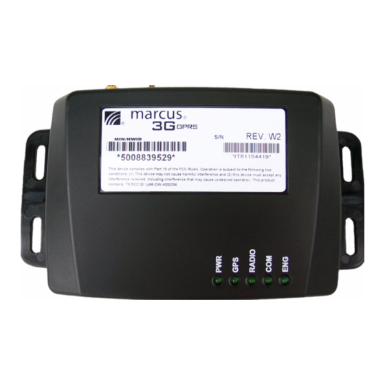
Description of Views
Top View with LEDs
MARCUS® 3G Radio Module
USB:
USB Connector Port
SIM DOOR: SIM Tray
PWR:
Device is powered
- GREEN Permanently ON - Device Functional
- Permanently OFF - No Power or Device Nonfunctional
GPS:
GPS fix is valid
RADIO:
GPRS modem transmitting
COM:
Device online with MARCUS® Servers
ENG:
Ignition is powered
- GREEN Permanently ON - Engine ON
- Permanently OFF - Engine OFF
Back View Connector Layout
MARCUS® 3G Radio Module Back View
Left Connector: (8 pin) Power 12 Volts DC 3 wire install with
optional Aux lines 3 Inputs / 2 Outputs
NOTE: Power connection must be wired in the following manner:
RED
Wire = Constant 12 Volts, Pin 7
Black Wire = Chassis Ground, Pin 8
White Wire = Switched Ignition, Pin 6
RS-232/DB9 Port: Serial port connector
Center Connector: GPS Connector / SMB Male Snap-on
Right Connector:
RF Connector / SMA Female Screw-on
MARCUS® 3G Radio Module Wiring Diagram
Combo GPS - Radio Antenna: Glass mount with TX/RX side toward the
glass on lower passenger side windshield.
NOTE: Sensors are connected through Pin 1-5. Power
connectors are through Pins 6-8.
AUX/I
Orange
wire; Pin 1 can be configured to monitor powered sensors
(+12 Volts trigger).
AUX/I
Green
wire; can be configured to monitor negative sensors (Ground
trigger).
Recommended that Constant and Switched power be wired through a
fused circuit (in-line fuse, 3 amps).
Important: Failure to properly wire the MARCUS® 3G Module will cause
faulty operation.
Appendix C:
Pictures and Diagram of the MARCUS® 3G Radio
MARCUS® 3G Radio Module Top View
MARCUS® 3G Radio Module Back View
MARCUS® 3G GPRS Radio Module
DW-A0003-W2
18