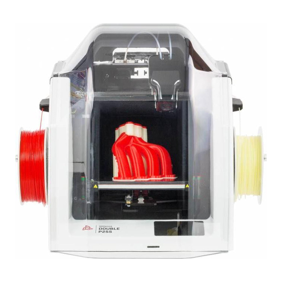
3DGence DOUBLE P255 Manuale di manutenzione - Pagina 9
Sfoglia online o scarica il pdf Manuale di manutenzione per Stampanti 3D 3DGence DOUBLE P255. 3DGence DOUBLE P255 19.

5. CALIBRATION OF OFFSETS ALONG X, Y AND Z AXES
Due to design characteristics of the dual hotend 3D printer, there are differences in the position of the hotends
along X, Y and Z axes. X/Y/Z Offset is the name of the parameter describing the position difference of T1 extruder
nozzle with respect to T0 extruder nozzle along X/Y/Z axes. Fig. 61 shows the visualization of the offsets along X axis
and Z axis. This difference can be compensated by the printer settings, using the touch panel.
Fig. 61 Visualization of the nozzle position difference (offsets)
ATTENTION: After each change of the hotend, the Z offset should be calibrated, and then the offsets along the X and
Y axis should be calibrated!
Calibration of Z axis offsets:
To calibrate the nozzle position difference along Z axis, use the Z MEASURE option available in MENU → ADVANCED
→ MODULE CALIB. The printer makes the tensometric measurement of the distance of both hotends (T0 and T1)
from the heatbed and recalculates these distances to the position difference of the T1 extruder nozzle with respect
to the T0 extruder nozzle.
The Z offset value can be also modified manually: MENU → ADVANCED → MODULE CALIB. → Z OFFSET and use the
+/- keys to enter a value.
Calibration of XY offsets:
In order to verify the offset along the X, Y axes, the calibration model should be printed in the printer memory
(procedure described below). The model is prepared for PLA and BVOH materials. The printout takes about 10
minutes. The model consists of two parts - part X (fig. 62) and part Y (fig. 63). Part X is used to set offset between
hotends along the X axis. Part Y is used to set offset between hotends along the Y axis. Each part consists of two
material layers - the bottom layer printed from support material (fig. 62, white) and the upper layer printed from
model material (fig. 62, red). Each part of the model is built of 11 lines. The middle line is point 0.00. The lines to the
right from point 0.00 increase with the plus sign every 0.05 mm in the range from 0.05 mm to 0.25 mm, and the lines
to the left from 0.00 point decrease with the minus sign every 0.05 mm in the range from -0.05 mm to - 0.25 mm
(fig. 62, 63). Printed symbols: "+" on the right side and "-" on the left side are helpful in determining the character
with which the read value will have to be entered into the printer (fig. 62, 63). With correctly calibrated offsets on
the middle line (point 0.00), the model material coincides with the support material both along the X axis and along
the Y axis.
3DGence DOUBLE P255 - maintenance activities | version 07.2021
