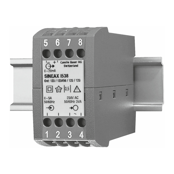
Camille Bauer SINEAX I 538 Manuale di istruzioni per l'uso - Pagina 9
Sfoglia online o scarica il pdf Manuale di istruzioni per l'uso per Trasduttore Camille Bauer SINEAX I 538. Camille Bauer SINEAX I 538 12. Transducer for ac current
Anche per Camille Bauer SINEAX I 538: Manuale di istruzioni per l'uso (12 pagine)

4. Mounting
The SINEAX I 538 can be mounted on a top-hat rail.
Note "Environmental conditions" in Section
"3. Technical data" when determining the place of
installation!
Simply clip the device onto the top-hat rail (EN 50 022) (see
Fig. 1).
Fig. 1. Mounting onto a top-hat rail 35 × 15 or 35 × 7.5 mm.
5. Electrical connections
Connect the leads acc. to the instructions on nameplate.
Make sure that all cables are not live when
making the connections!
Impending danger by high power supply
voltage!
Take care of current transformers!
Also note that, ...
... the data required to carry out the prescribed mea-
surement must correspond to those marked on the
nameplate of the SINEAX I 538 (
input,
measuring output and
supply, see Fig. 6)!
... the resistance in the output circuit
– may not overrange the value
R
max. [kΩ] ≤
ext
(I
= current output end value)
AN
– with power supply via output leads (2-wire
connection, output 4 - 20 mA) dependent on
power supply H (12 - 32 V DC)
1000
600
0
0
H = Power supply [V]
R
max. [kΩ] =
ext
– may not underrange the value
R
min. [kΩ] ≥
ext
(U
= voltage output end value)
AN
... the measurement output cables should be twisted
pairs and run as far as possible away from heavy
current cables!
In all other respects, observe all local regulations when
selecting the type of electrical cable and installing them!
measuring
power
15 V
I
[mA]
AN
12
24
32
H [V] – 12 V
20 mA
U
[V]
AN
10 mA
– +
5 6 7 8
1 2 3 4
I
Fig. 2. AC power supply
-
R
ext
+
–
+
5 6 7 8
1 2 3 4
I
Fig. 4. Power supply via
output leads.
I
= Current measuring input
= Power supply
Measuring output
Test marks on
5 6 7 8
device rear side
0–20 mA
SINEAX I 538
Ord: 123 / 123456 / 123 / 123
Works No.
0–5A
50/60Hz
1 2 3 4
Measuring input
Fig. 6. Declaration to type label.
– +
5 6 7 8
1 2 3 4
– +
I
Fig. 3. DC power supply.
– +
5 6 7 8
1 2 3 4
–
I
Fig. 5. DC, AC power supply,
in version with built-in
DC, AC power pack.
= Measuring output
Optionally with
potentiometer
for variable
sensibility ±10%
Camille Bauer AG
Manufacturer
Switzerland
0,5
3,7
230V AC
50/60Hz 3VA
Power supply
9
