esera DS18S20 Manuale d'uso - Pagina 2
Sfoglia online o scarica il pdf Manuale d'uso per Accessories esera DS18S20. esera DS18S20 4. 1-wire temperature sensor
2
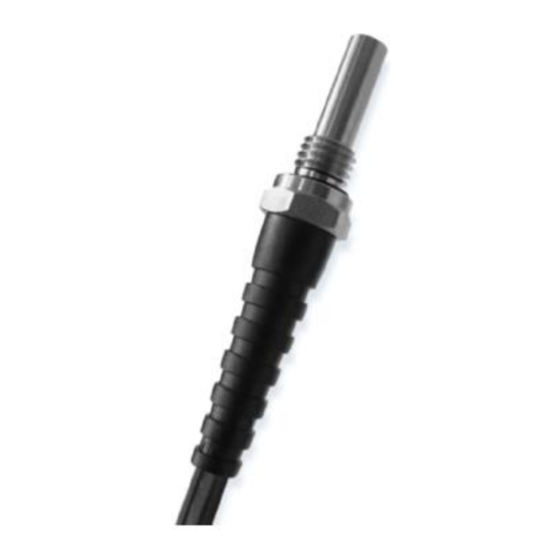
Technical data Sensor
1-Wire module:
Accuracy:
Resolution:
Operating voltage:
Power consumption:
Connection cable:
Mechanics:
Dimensions:
ambient conditions (cable): Operation: moving -10 ... +60 °C, unmoved -40 ... +80 °C, briefly 100 °C
3
Auto-E-Connect® Support
The ESERA Auto-E-Connect® 1-Wire Plug and Play system will be used for the
1-Wire Bus supported. This enables fully automatic configurations of 1-Wire sensors
and actuators on the 1-Wire bus. It is optimized for industrial applications and
enables significant added value beyond the sensor and chip data.
The Auto-E-Connect function automatically recognizes ESERA chips, sensors and actuators, starts suitable
libraries and outputs fully formatted data.
The Auto-E-Connect functionality will be available from mid-2020 via 1-Wire Controllers, 1-Wire Gateways and
1-Wire ECO from ESERA available.
Further information on ESERA Auto-E-Connect can be found on the ESERA website, ESERA Config-Tool 3, or in
the download area for this article in the ESERA Webshop.
4
Pin assignment
The Western connector is assigned as follows (view of the cable, i.e. the contact surfaces of the connector):
1
Shielding or unoccupied
2
Ground
3
Dallas Data or unoccupied
4
Dallas Data
5
+5 V
6
+5 V or unoccupied
Note, the sensor cannot be connected directly to the 1-Wire adapter because of different pin assignments!
Note: Basic information and tips on the 1-Wire Bus system can be found on the ESERA website at:
https://www.esera.de/1-wire-grundlagen/
5
1-Wire Network
For short connection lengths, no special requirements are placed on the cable used. With unshielded cable, a
longer connection length can be achieved in an undisturbed environment, since the capacitive bus load is lower.
A total length of 60 m and more can be achieved without additional measures.
In a disturbed environment, the cable should be shielded to improve the interference sensitivity of the system.
Due to the higher capacitive load, the maximum possible connection length is reduced.
The special feature of the wiring of the sensors is the "BUS technology": All sensors are operated in parallel on a
three-core cable, via which both the power supply and the data communication take place.
Increase the connection length:
The sum of all connecting cables should be less than approx. 60m to ensure safe operation. By connecting an
additional pull-up resistor with 4.7 ... 10 kOhm (line DATA against +5 V) the cable length can be increased, but
with a slight deterioration of the measuring accuracy due to the higher self-heating of the sensor.
All rights reserved. Reproduction as well as electronic duplication of this user guide, complete or in part, requires the written consent of
ESERA GmbH. Errors and technical modification subject to change. ESERA GmbH, ESERA-Automation 2020
www.esera.de
DS18S20
+/- 0,5°C in the range of -10°C to 85°C
9 Bit, 0,5°C to 0,0625°C/Bit depending on readout method
5 V= (+/-5%)
approx..1mA
2m
thread 1/8 inch
Immersion sleeve in front of thread: 20mm,
Thread height: 8mm
Wrench size: 14mm
Total length:
35mm (without cable)
bend relief:
47mm
11119 V2.0 R1.0 Manual
Page 2 of 4