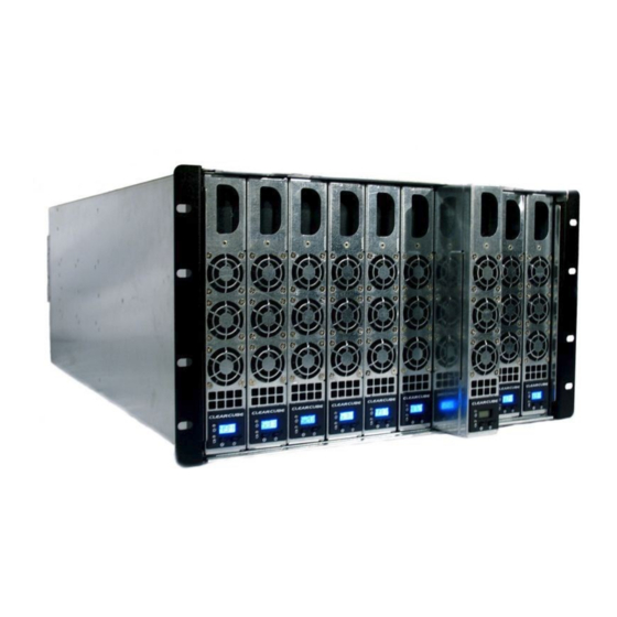
ClearCube A1410 Manuale di avvio rapido
Sfoglia online o scarica il pdf Manuale di avvio rapido per Server ClearCube A1410. ClearCube A1410 2. I/port
Anche per ClearCube A1410: Manuale di avvio rapido (2 pagine), Manuale di avvio rapido (2 pagine), Avvio rapido (2 pagine), Manuale di avvio rapido (2 pagine)

V5120 Dual Host Card Upgrade Kit for A1410 Blades
The V5120 Dual Host Card Upgrade Kit for A1410 blades
contains the following items:
V5120 Dual Host card—Provides
dual–monitor support.
Riser card—Attaches to V5120 card and to
blade motherboard
Mounting hardware—Two pan–head screws,
two SEMS screws, and two male–female
standoff screws
Support bracket
Mounting bracket
Ethernet cable
Four–pin signal cable
Video V5120 configuration label—Provides
5120
part number, serial number, and card MAC
address. MAC address is critical for card and
blade configuration.
Note: The upgrade kit is for A1410 blades only.
System Firmware Compatibility
Ensure that the V5120 Dual Host card in your blade and the user
port to which the blade connects (I9420 I/Port thin client or C7420
C/Port) contain the compatible versions of firmware. For more
information, see support.clearcube.com.
Installing the V5120 Dual Host Card
Perform the following steps to install the V5120 upgrade kit. Use a #2
Phillips head screwdriver and, optionally, a ¼–inch hex–head wrench.
1.
Remove the A1410 blade from the chassis. If the blade is not in a
chassis, ensure that you disconnect power from the blade.
2.
Remove the three screws from the top cover and remove the
cover from the blade.
ClearCube Technology
Quick Start Guide
8834 Capital of Texas Hwy N
Austin, Texas 78759
3.
Remove the three screws from the I/O cover, located above the
power supply on the rear of the blade.
4.
Remove the two pan–head screws shown in the following figure
(the small heat sink is omitted for clarity). Insert the two standoff
screws (included in the kit) in the same holes. Use a hex–head
wrench to gently tighten the standoff screws.
5.
Attach the support bracket to the standoffs using the 2 pan–
head screws you previously removed from the motherboard.
Ensure that the card support rails face up and face away from the
heat sink (heat sink omitted in the following figure).
6.
Attach the V5120 card to the mounting bracket using the two
pan–head screws included in the upgrade kit. Ensure that the
Ethernet port is facing down, as shown in the following figure.
voice 512 652 3500 www.clearcube.com
Remove
I/O cover screws.
Remove screws and save.
Insert standoff screws in
same holes.
Ethernet Port
