dixell XR06CX Manuale operativo - Pagina 3
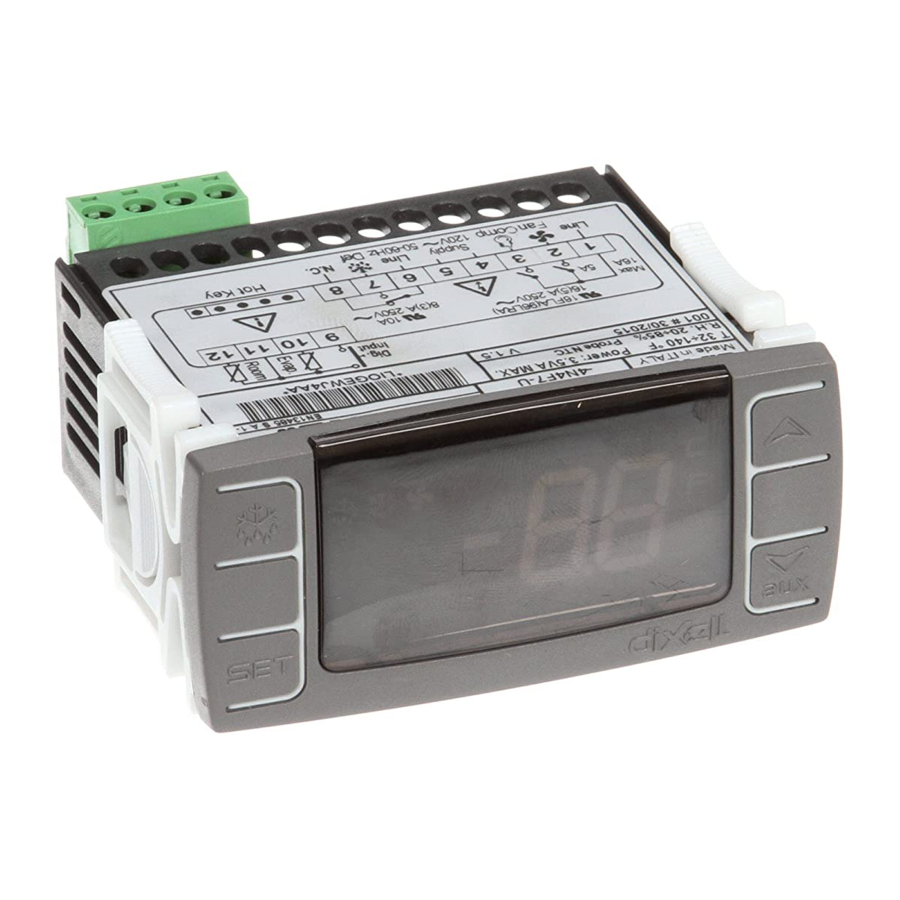
Sfoglia online o scarica il pdf Manuale operativo per Router di rete dixell XR06CX. dixell XR06CX 3. Digital controller with defrost and fans management
Anche per dixell XR06CX: Manuale (2 pagine)

Mounting: panel mounting in a 71x29mm panel cut-out
Protection: IP20; Frontal protection: IP65
Connections: Screw terminal block ≤ 2,5 mm
Power supply: according to the model 230Vac ±10%, 50/60Hz --- 110Vac ±10%, 50/60Hz
Power absorption: 3.5VA max
Display: 2 digits, red LED, 14,2 mm high; Inputs: Up to 2 NTC.
Digital input: free voltage contact
Relay outputs: compressor SPST 8(3) A, 250Vac; SPST 16(6)A 250Vac or 20(8)A 250Vac
defrost: SPDT 8(3) A, 250Vac
fan: SPST 8(3) A, 250Vac or SPST 5(2) A
Data storing: on the non-volatile memory (EEPROM).
Kind of action: 1B; Pollution grade: 2;Software class: A.;
Rated impulsive voltage: 2500V; Overvoltage Category: II
Operating temperature: 0÷60 °C;Storage temperature: -25÷60 °C.
Relative humidity: 20÷85% (no condensing)
Measuring and regulation range: NTC -40÷110°C;
Resolution: 0,1 °C or 1°C or 1 °F (selectable); Accuracy (ambient temp. 25°C): ±0,1 °C ±1 digit
15. CONNECTIONS
15.1 XR06CX – 20+8+5A OR 16+8+5A – 110VAC OR 230VAC
NOTE: The compressor relay is 20(8)A or 16(6)A depending on the model.
NOTE: Connect the 120Vac power supply to 4-5
15.2 XR06CX -- 8+8+8A -- 110VAC OR 230VAC
NOTE: Connect the 120Vac power supply to 6-7
16. DEFAULT SETTING VALUES
LAB
DESCRIPTION
EL
REGULATION
Hy
Differential
LS
Minimum Set Point
US
Maximum Set Point
ot
First probe calibration
P2
Second probe presence
oE
Second probe calibration
od
Outputs activation delay at start up
AC
Anti-short cycle delay
Cy
Compressor ON time faulty probe
Cn
Compressor OFF time faulty probe
DISPLAY
CF
Measurement units
rE
Resolution (only for °C)
Ld
Default Display
dy
Display delay
DEFROST
td
Defrost type
dE
Defrost termination temperature
Operating Manual
wiring.
2
RANGE
0.1 ÷ 25°C/1 ÷ 45°F
-55°C÷SET/-67°F÷SET
SET÷99°C/ SET÷99°F
-9.9÷9.9°C/-17÷17°F
n – Y
-9.9÷9.9°C/-17÷17°F
0 ÷ 99 min
0 ÷ 50 min
0 ÷ 99 min
0 ÷ 99 min
°C - °F
dE – in
P1 - P2 - SP
0 ÷ 15 min
EL – in
-55÷50°C/-67÷99°F
id
Interval between defrost cycles
Md
Maximum length for defrost
dd
Start defrost delay
dF
Display during defrost
dt
Drip time
dP
Defrost at power-on
FANS
FC
Fans operating mode
Fd
Fans delay after defrost
FS
Fans stop temperature
ALARMS
AU
Maximum temperature alarm
AL
Minimum temperature alarm
Ad
Temperature alarm delay
Exclusion of temperature alarm at
dA
startup
DIGITAL INPUT
iP
Digital input polarity
iF
Digital input configuration
di
Digital input delay
Compressor and fan status when open
dC
door
rd
Regulation with door open
OTHER
d1
Thermostat probe display
d2
Evaporator probe display
Pt
Parameter code table
rL
Firmware release
DEFAULT
2.0°C / 4 °F
-55 °C /-
55°F
99 °C /
99°F
0.0
y
0.0
0
1
15
30
°C / °F
dE
P1
0
EL
8.0 °C / 46
°F
0 ÷ 99 hours
6
0 ÷ 99 min.
30
0 ÷ 99 min.
0
it
rt – in – SP – dF
0 ÷ 99 min
0
y - n
n
cn – on – cY – oY
on
0 ÷ 99 min
10
2.0 °C / 36
-55÷50°C/-67÷99°F
°F
99 °C / 99
ALL÷99°C / ALL÷99°F
°F
-55°C÷ALU/-
-55 °C / -
67°F÷ALU
55 °F
0 ÷ 99 min
15
0 ÷ 99 min
90
cL – oP
cL
EA – bA – do – dF – Au
EA
– Hc
0 ÷ 99 min
5
no /Fn / cP / Fc
FC
n - Y
y
Read Only
- - -
Read Only
- - -
Read Only
- - -
Read Only
- - -
3/3
