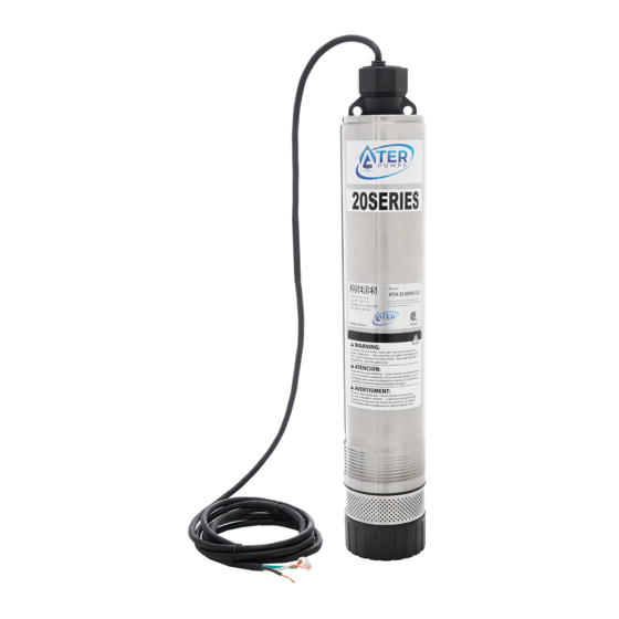
ClearStream P35-2 Series Manuale d'uso - Pagina 3
Sfoglia online o scarica il pdf Manuale d'uso per Pompa dell'acqua ClearStream P35-2 Series. ClearStream P35-2 Series 4. 4” submersible pump

PUMP INSTALLATION
1. Make sure that pump and motor are free to rotate by turning
theshaft by hand.
2. To prevent dropping pump, lower it by the drop pipe, not by
thecables. The electrical cables will not hold the pump weight.
3. Discharge outlet is 1-1/4" NPT threaded.
NOTICE: Pump discharge is left-hand thread into pump shell. If
installing external check valve, hold discharge with pipe wrench
to prevent loosening discharge in shell.
4. If pump is to be operated with an open discharge, a discharge
valvemust be installed. * Before startup, open this valve about 1/3
open.
HP
1/2
1
Volts
HP
14 AWG
115
1/2
100
230
1
250
1. Maximum wire lengths shown maintain motor voltage at 95% of
service entrance voltage, running at maximum nameplate amperes. two sizes larger (i.e., if #12 copper wire, use #10 If service
entrance voltage will be at least motor nameplate voltage aluminum wire. under normal load conditions, 50% additional
length is permissible for all sizes.
Normal Ohm/Megohm readings for all motors, between all leads and ground. Set ohmmeter to 100K scale.
Condition of Motor and Leads
New Motor , without power cable
Used motor, which can be reinstalled in tank
New Motor
in reasonably good condition
Motor which may be damaged or have damaged power cable
Do not pull motor for these reasons
Motor definitely damaged or with damaged power cable
Pull motor and repair
Failed motor or power cable-Pull motor and repair
Table 1: Recommended Fusing Data
60 Hz/1 Phase 2-Wire Cable
Motor Winding
Volts/Hz/
Resistance
Phase
Ohms
115/60/1
1.0-1.3
230/60/1
2.2-2.7
Table 2: Power Supply Wire (Cable) Length in Feet
1 Phase, 2 Wire Cable, 60 Hz (Copper Wire Size – Service to motor)
12 AWG
10 AWG
160
250
400
630
Motor Insulation Resistance Readings
Motor in Tank – Readings are Power Cable plus Motor
Start pump. Slowly open valve until the desired flow rate is reached. Final
setting must be within pump's recommended operating range.
1.
The pump must be submerged at all times during normal
operation.
Do not run pump dry.
2.
Make sure that the float switches are set so that the pump stops
before the pump runs dry or breaks suction. If necessary, adjust
float switches to achieve this.
3.
The motor bearings are lubricated internally. No maintenance is
required or possible on the pump or the motor.
Max
Load
Amps
7.8
9.8
8 AWG
6 AWG
4 AWG
390
620
960
940
1540
2380
2. Sizes given are for copper wire. For aluminum wire go
Ohm Value
20,000,000
10,000,000
2,000,000 (or more)
500,000 t0 2,000,000
20,000 to 500,000
10,000 to 20,000
Less than 10,000
OPERATION
Locked
Fuse Size
Rotor
Standard
Amps
Dual Element
21
20/15
48.7
25/12
3 AWG
2 AWG
1 AWG
1190
1460
2960
3610
Megohm Value
0.5-2.0
2
0 AWG
1780
2160
4410
5360
20.0
10.0
2.0 Motor
0.02-0.5
0.01-0.02
0-0.1
