EDI 222 Series Manuale operativo - Pagina 11
Sfoglia online o scarica il pdf Manuale operativo per Sensori di sicurezza EDI 222 Series. EDI 222 Series 17. Inductive loop detector sensor unit

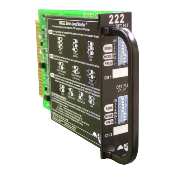
Each channel is fitted with a high intensity RED detect LED indicator (DET) and a Yellow Fault
LED indicator (FLT).
Front Panel Controls:
Front panel mounted DIP switches allow the user to set up sensitivity, operational mode,
frequency and channel OFF/ ON state independently for each channel.
Sensitivity:
One of eight settings may be selected to optimize
detection on varying loop and lead-in configurations.
Sensitivity is stated in terms of ∆L/L, i.e. the minimum
percentage change in the total inductance (loop plus
lead-in) to which the unit will respond at the given
level setting.
Channel ON/OFF:
Selecting Channel OFF will disable the channel. In this condition, the loop oscillator is de-
energized, and the output will remain in the no-call state.
Operational Modes:
Pulse Mode (PL):
Short Presence (SH):
Long Presence (LG):
When the jumper labeled SEL3 is inserted, the Model 222 will limit the minimum presence time
to 100 milliseconds.
When operating in pulse mode, a vehicle remaining over a loop will inhibit further pulse outputs
from being issued for a period of 2 seconds after which time vehicles passing over the
uncovered portion of the loop will be detected.
Frequency:
One of four settings may be selected to alleviate interference which may occur when loops
connected to different detectors are located adjacent to one another.
Reset Input:
The Model 222 may be reset by applying a ground true logic level to the Reset input pin J1-C.
Response Times:
The following are typical response times at different sensitivity levels. Note: the times indicated
are valid when both channels are set to the same sensitivity operating at approximately
40KHz.
Eberle Design Inc.
Model 222
Operations Manual
125 25 milliseconds momentary output
30 minutes maximum
120 minutes maximum
SENS
Response
Time
Level 7
40 15 ms
19 7 ms
Level 6
Level 5
9 3 ms
5 1.5 ms
Level 4
SENS
Level 7
Level 6
Level 5
Level 4
SENS
Response
Time
Level 3
2.8 1 ms
2.5 1 ms
Level 2
Level 1
2.5 1 ms
2.5 1 ms
Level 0
∆L / L
SENS
∆L / L
0.01%
Level 3
0.16%
0.02%
Level 2
0.32%
0.04%
Level 1
0.64%
0.08%
Level 0
1.28%
Page 9
