EDI 222 Series Manuale operativo - Pagina 8
Sfoglia online o scarica il pdf Manuale operativo per Sensori di sicurezza EDI 222 Series. EDI 222 Series 17. Inductive loop detector sensor unit

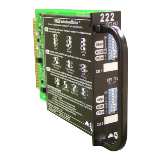
Front panel switch settings are read directly by the microcontroller parallel ports P3 and P4. The Call
Output opto-isolator U1 (U2) is driven directly by the microcontroller port P1_2 (P1_3). The front
panel LED indicators DS1 (DS2) are similarly driven by the microcontroller port P5.
Monolithic regulator VR1 provides a stable 5 volt DC power supply to the digital circuitry and loop
oscillators. The Model 222 will operate properly until the power input at pin J1-B drops below 8 VDC.
1.7 MAINTENANCE
1.7.1 TROUBLE ANALYSIS
The following list should be used to trouble-shoot the Model 222 installation. If the detector unit itself
is suspect, see Section 1.7.2 for a complete internal testing sequence.
a. Neither channel responds to vehicles.
a. Power supply fault.
The Model 222 requires a 24 VDC nominal supply. Each unit draws between 40mA and 80mA
depending on detect status. The unit will operate at voltages as low as 8 Vdc, however, supply
voltage below this may result in the unit entering a reset state. In this case, the unit will appear
to be non-functional.
b. Reset line held low.
This fault is likely to affect all units in the rack since the external reset line is typically common
to every rack position. Measure the voltage on the External Reset line (pin J1-C). If it is below
15 volts, remove each unit one by one until the next line returns to the power supply level. The
unit that was removed last should be checked carefully for other faults. See Section 1.7.2.
b. Channel does not detect all vehicles.
a. Sensitivity too low.
Increase sensitivity by one setting and observe detection.
c. Channel is noisy or chatters and outputs false detect calls.
a. Two or more units are interfering with each other (crosstalk).
Check frequency settings on units which are connected to loops closest to the one exhibiting
crosstalk; several may be showing signs of crosstalk themselves. Adjust the frequency
switches on all units and all channels affected so that the largest possible margin exists
between frequencies of loops positioned the closest.
b. Poor connections
Loop connections are very important to the satisfactory operation of the sensor unit. All
connections whether they are in the cabinet or at the roadside must be secure, must be
soldered and, in the case of connections made at the roadside, waterproofed to prevent
shorting to ground.
c. Poor loops
Loops which have become degraded due to the passage of traffic may cause the unit to exhibit
crosstalk like symptoms. It may be possible to reduce the sensitivity while maintaining
adequate detection of vehicles. However, the ideal solution is to replace the loop.
Eberle Design Inc.
Model 222
Operations Manual
Page 6
