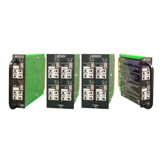
EDI LMD602T Series Manuale operativo - Pagina 11
Sfoglia online o scarica il pdf Manuale operativo per Sensori di sicurezza EDI LMD602T Series. EDI LMD602T Series 15. Deflectometer inductive loop monitor

The typical sensing height is 2/3 of the shortest leg of a loop (in feet). Therefore a 4' x 8'
loop typically has a detection height of 2.6'.
The inductance of a conventional four-sided loop can be estimated using the formula:
2
L = P x (T
Therefore a 4' x 8' loop with 3 turns would be:
L = (4 + 8 + 4 + 8) x (3
L = 24 x (9 + 3) / 4
L = 24 x 12 / 4
L = 72 microHenries
Note: Loop feeder cable typically adds 0.22 microHenries of inductance per foot of cable.
The following are suggested guidelines for loop installation:
To begin, make sure that the pavement surface in the area that loops are to be installed is
dry and free of debris. The outline of the loop(s) should be marked on the pavement in such
a way that the lines can be followed easily by the saw operator and not be erased by the
water feed from the saw itself.
All 90-degree corners should be chamfered so that the course of the loop wire does not
change direction sharply but rather at shallower angles of 45 degrees or less. Core drilling
of the corners achieves the same effect but can still lead to failure due to sharp edges
remaining in the corner area. When the outline of the loop and lead-in has been marked,
the pavement can be cut. Diamond blade cutting saws are recommended. The saw cut
should be approximately 2.0 inches deep and 0.25 inches wide. The saw slot should then
be cleaned out and allowed to dry. Compressed air is useful both for ejecting debris and
speeding up the drying process. All debris in the vicinity of the saw slot should also be
removed so that it is not accidentally pushed back in.
As a general rule loops with circumference lengths less than 12 feet require 5 turns of wire,
12 to 60 feet require 3 to 4 turns of wire, loops with greater circumference lengths should
have 2 to 3 turns.
Recommended loop wire is typically 14, 16, 18, or 20 AWG with cross-linked polyethylene
insulation. Since moisture can cause significant changes in the dielectric constant of the
insulation, which results in excessive loop (frequency) drift, choose insulation, which is
most impervious to moisture. PVC, TFFN, THHN, and THHN-THWN should be avoided
since they tend to absorb moisture and crack easily. XLPE (Cross Linked Polyethylene) is
very resistant to moisture absorption and provides good abrasion resistance.
If long lead-ins are required, it is suggested that the loop cable be spliced onto shielded,
pre-twisted, lead-in wire (IMSA specification 50-2 is suggested) at a convenient pull box
location close to the loop. The shield may be connected to earth at the cabinet end but
should then be insulated and isolated from earth ground at the loop end. The inductance of
the loop itself should be at least 50% of the sum of loop inductance plus lead-in inductance.
Start laying the loop wire from the termination of the lead-in out towards the loop, continue
around the loop for the number of turns required and finally return to the lead-in
termination. Leave the lead-in wire out of the slot so that it may be twisted together before
being laid in the slot. Lead-ins should be twisted with a minimum of 4 to 6 twists per foot to
prevent any separation of the lead-in wires.
Make sure that the loop wire is pushed fully to the bottom of the saw slot. Small pieces of
foam rubber (backer rod) or similar material may be used at various points around the
Eberle Design Inc.
LMD602 and LMD604 Series
Operations Manual
Section 3
Loop Installation
+ T) / 4 Where
L = Loop Inductance in microHenries
P = Loop Perimeter in feet
T = Number of wires in saw slot
2
+ 3) / 4
Page 8
