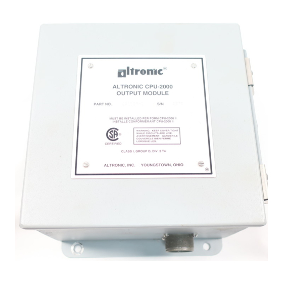
Altronic CPU-2000 Istruzioni di servizio - Pagina 13
Sfoglia online o scarica il pdf Istruzioni di servizio per Sistemi di controllo Altronic CPU-2000. Altronic CPU-2000 20. Ignition system

3.0 TEST STAND REQUIREMENTS
3.1 In order to test an Altronic CPU-2000 ignition system, a special test stand is required. The basic test
stand is similar to that required for the Altronic II-CPU system.
3.2 The following items are required to test the Altronic CPU-2000 system:
A variable speed motor of 0.5 HP or greater, capable of rotating 1500 RPM with a standard
A
ignition drive accepting either flange or base mounting.
B.
A spark degree wheel graduated in 360 increments with the indicator attached to the shaft
driving the Altronic II unit.
C.
Sixteen (16) 291001 ignition coils connected to suitable, adjustable spark gaps. NOTE: The test
stand should incorporate thirty-two (32) ignition coils if 32-output units are tested.
D.
A source of gear tooth pulses mechanically connected to the Altronic II unit drive; a 180-tooth
gear is recommended.
E.
A single reset pin (6-32 steel machine screw recommended) mounted to the face of the gear.
F.
Magnetic pickups (691118-x) mounted to sense the gear teeth (A) and the reset pin (B).
G.
A primary wiring harness connecting the ignition coils to the CPU-2000 Output Module. This
requires connector MS3108A-22-14S, Altronic part number 504056. NOTE: Two harnesses are
required to test 32-output units.
H.
A 581602 manual control loop unit to simulate the 4-20mA control signal.
I.
A DC power source capable of supplying 24Vdc, 10 amps - see Installation Instructions form
CPU-2000 II, section 10.4 and drawing 209 120.
J.
An Altronic II-CPU Alternator; part no. 290213H is recommended. A distributor shaft assembly
with 2: 1 gear installed is required to test a 4-cycle application. The rotating magnet on the
distributer shaft assembly must be over the Hall-effect switch when the reset pin on the test
stand is opposite its magnetic pickup.
K.
An Altronic II-CPU back cover assembly 281500-1 or -2 and mating harness 293024-1. Connect
the wiring harness as shown on the following page.
L.
A blank CPU-2000 EEPROM, Altronic part number 601668-A. Test memories can be used if
the Terminal Program is not used. Test memories for 16 and 32-cylinder, 4-cycle applications
programmed with the number of teeth used on the test stand (usually 180) will be needed.
M .
Altronic CPU-2000 Terminal Program part number CPU-2000.MEM.
NOTE: Reference form CPU-2000 Pl, section 1.3 for computer and peripheral requirements for
the Terminal Program.
N.
A means to elevate CPU-2000 Output Module to a controlled temperature of 150
0.
A 293030-25 cable to connect the Logic Module to the Output Module.
NOTE: Altronic Test Unit 791025-1 can provide simulated pickup signals to exercise the CPU-
2000 outputs at a fixed firing rate.
P.
The optional CPU-2000 Diagnostic Module 291105-1 can be adapted using harness 293031 and
a 3-conductor cable 593050 as shown in the Test Stand Wiring diagram.
-13-
°
°
F. (65
C.).
