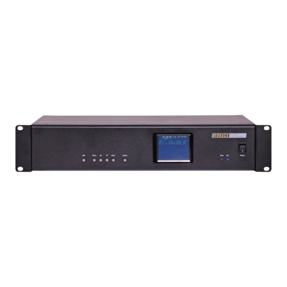
Altronics Redback A 4510 Manuale operativo - Pagina 10
Sfoglia online o scarica il pdf Manuale operativo per Timer Altronics Redback A 4510. Altronics Redback A 4510 12. Yearly timer
Anche per Altronics Redback A 4510: Manuale di programmazione software (16 pagine)

A 4510 Yearly Timer
2.6 24V OUTPUT CONNECTIONS
These contacts can be used for connection of override relays in remote volume controls, or for operating an external relay
used to operate something like a school bell etc.(Note: These 24V DC outputs are limited to 120mA maximum current draw).
Prebell 24V Out:
These contacts are for switched 24V outputs whenever the Bell tone is activated. These may be used to run external systems
such as override relays in remote volume controls.
When this output becomes active, 24V will appear between the N/O contact and the GND contact. When this output is not
active 24V will appear between the N/C contact and the GND.
Music 24V Out:
These contacts are for switched 24V outputs whenever the Music tone is activated. These may be used to run external sys-
tems such as override relays in remote volume controls.
When this output becomes active, 24V will appear between the N/O contact and the GND contact. When this output is not
active 24V will appear between the N/C contact and the GND.
Bell 24V Out:
These contacts are for switched 24V outputs whenever the Bell or Relay Only (No MP3 option) are activated These contacts
are for operating an external relay used to operate something like a lunch bell etc.
When this output becomes active, 24V will appear between the N/O contact and the GND contact. When this output is not
active 24V will appear between the N/C contact and the GND.
Common 24V Out:
These contacts are for switched 24V outputs whenever the Bell, Prebell, Music or Relay Only (No MP3 option) tones are
activated. When this output becomes active, 24V will appear between the N/O contact and the GND contact. When this
output is not active 24V will appear between the N/C contact and the GND.
2.7 BATTERY BACKUP (TIME)
On the rear of the unit is a switch labelled Battery Backup. This is used to backup the internal clock in the event of a power
failure. The switch is set to OFF by default to ensure the backup battery isn't discharged.
(NOTE: this does not provide backup power to the unit itself. If a power fail backup supply is required this must be
connected to the 24V DC input).
A power fail will not mean a loss of the programmed events, as they are stored on the SD card. Once power is restored the
unit will power up and read the events from the SD card and operate as normal.
10
Redback® Proudly Made In Australia
Setup
www.altronics.com.au
