Altronix AL642ULADA Manuale di installazione - Pagina 7
Sfoglia online o scarica il pdf Manuale di installazione per Estensore Altronix AL642ULADA. Altronix AL642ULADA 17. Nac power extenders
Anche per Altronix AL642ULADA: Manuale di installazione (17 pagine), Manuale di installazione (16 pagine), Manuale di applicazione (8 pagine), Manuale di applicazione (8 pagine)
* Indicates existing trouble condition. When a trouble condition (open, short or ground) occurs on a specific output, the
corresponding red output LED, [OUT1-OUT4] will blink. The corresponding green input LED will blink as well.
** Indicates trouble condition memory. When a trouble condition restores, the units red output LEDs, [OUT1-OUT4]
will blink with a shorter and distinctly different duration. The green input LEDs will be off (normal condition).
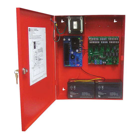
To reset the memory depress the reset button located on the AL842LGK logic board (Fig. 2c, pg. 7).
The LED(s) will extinguish.
Note: When indicating circuits have restored, trouble memory reset is not required for normal operation.
Fig. 2
unswitched 120VAC
60Hz, 5 amp
power mains
(non power-limited)
Line
Ground
Neutral
Green Lead
Fig. 2b
These circuits are used to monitor
AC and Bat Fail and will cause a
simultaneous trouble condition
to the FACP's IN1 and IN2
(Non-Supervised)
AL642ULADA
Factory Installed
Board Interface
Hookup Diagram:
Cable
Divider
Non-power limited
Supervised
Non-power limited
Th is connection is used to monitor
AC and Bat Fail and will cause a
simultaneous trouble condition
to the FACP's IN1 and IN2
(Non-Supervised)
Addressable
control module
trigger output
NC "DRY2" C
-- RET2 +
NC "DRY1" C
-- IN2 +
Addressable
control module
(See Typical Application Diagram for device hookup)
trigger output
Power Limited Inputs
Non-Supervised
Supervised
NC "DRY2" C
-- RET2 +
-- RET1 +
NC "DRY1" C
-- IN2 +
-- IN1 +
Factory Installed
Board Interface
Cable
OUT1
FAULT
INP2 INP1
INPUT SELECT
OUT2
OUT1 OUT2 OUT3 OUT4
INPUT SELECT
Magnetic
Door Holder
FAULT
INP2 INP1
OUT1 OUT2 OUT3 OUT4
+
--
4-wire Smoke
Detector
Fire
Alarm
Magnetic
Control
Panel
Door Holder
(FACP)
+
4-wire Smoke
Detector
Fire
Alarm
Control
Panel
(FACP)
(See Typical Application Diagram for device hooku
Power-Limited Outputs 2.5 amp per output max.
-- RET1 +
-- LOOP1 +
-- IN1 +
-- OUT1 +
Regulated Power-Limited Outputs 2.5 amp max.
per output max.
(total = 6.5 amp)
Non-Supervised
(Supervised)
-- LOOP1 +
-- LOOP2 +
-- LOOP3 +
-- LOOP4 +
-- AUX2 +
-- OUT1 +
-- OUT2 +
-- OUT3 +
-- OUT4 +
-- AUX1 +
OUT3
IN>OUT SYNC
STROBE SYNC
TEMPORAL
OUT4
RESET
IN>OUT SYNC
STROBE SYNC
TEMPORAL
+ DC ---
OUT1
OUT3
IN>OUT SYNC
STROBE SYNC
TEMPORAL
INPUT SELECT
OUT4
OUT2
IN>OUT SYNC
STROBE SYNC
TEMPORAL
INPUT SELECT
+ DC ---
+
--
4-wire Smoke
Detector
EOL Power
Supervision Relay
(Not Supplied)
EOL Resistor
from FACP
--
(total = 10 amp)
-- LOOP2 +
-- LOOP3 +
-- LOOP4 +
-- OUT2 +
-- OUT3 +
Fig. 2a
AC
Fig. 2c
RESET
Trouble Memory
Reset Button
+
--
4-wire Smoke
Detector
EOL Resistor
from FACP
- 7 -
-- A
-- OUT4 +
-
Su
(