Altronix NetWaySP1BTWPN Manuale di installazione - Pagina 4
Sfoglia online o scarica il pdf Manuale di installazione per Convertitore multimediale Altronix NetWaySP1BTWPN. Altronix NetWaySP1BTWPN 8. 802.3bt media converter/injectors
Anche per Altronix NetWaySP1BTWPN: Manuale di installazione (12 pagine)
Wiring methods shall be in accordance with the National Electrical Code/NFPA 70/ANSI, and with all local codes
and authorities having jurisdiction . All units should be installed by a trained service personnel .
Installation:
NetWaySP1BT:
1 . Mount NetWaySP1BT in desired location utilizing the mounting hole (Fig. 1a, pg. 4) . Use a proper fastener
and/or wall anchor when securing NetWaySP1BT with screw through its mounting hole to the surface .
Note: Earth ground can be used, if needed, for high transient or outdoor environments.
If used, insert an Earth ground wire (included with product) into the internal ground terminal until
secured (a slight tug can check stability) & fasten the free end to a chassis earth ground.
If earth ground is not attached and needed, refer to Fig. 3, pg. 5 for manual placement.
NetWaySP1BTWPN:
2 . Remove backplane from enclosure prior to drilling . Do not discard hardware .
Note: Make sure that hardware will not interfere with components of the circuit board .
3 . Mark and drill desired inlets on the enclosure to facilitate wiring. Maximum NEMA type 4X rated fittings
to be used are 0 .5" . Follow manufacturer's specifications for the appropriate size opening .
Note: Inlets for conduit fittings should only be made on the bottom of the enclosure .
To facilitate wire entry utilize weather-tight NEMA rated connectors (supplied), bushings, and cable .
4 . Clean out the inside of enclosure before remounting circuit boards/backplane .
5 . Mounting NEMA4/4X rated enclosure (Enclosure Dimensions, pg. 7):
Wall mount:
Pole Mount:
6 . Mount backplane in enclosure with hardware .
Power Connection:
1 . Use external 48-55V UL Listed ITE power supply, carefully observing correct polarity (Fig. 1, 2, pg. 4) .
2 . Use 14AWG or larger for all power connections .
Keep power-limited wiring separate from non power-limited wiring by utilizing separate knockouts/
inlets. Minimum 0.25" spacing must be provided.
CAUTION: Do not touch exposed metal parts. Shut branch circuit power before installing or servicing
equipment. There are no user serviceable parts inside. Refer installation and servicing to qualified
service personnel.
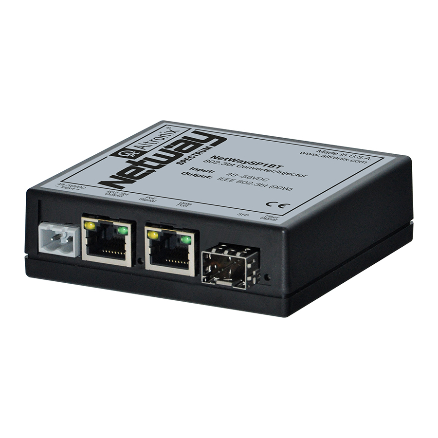
NetWaySP1BT
Fig. 1
NetWaySP1BT
802.3bt Converter/Injector
Input:
Output: IEEE 802.3bt (90W)
48-56VDC
802.3bt
-- Input +
Output
Optional
Earth
Ground
48-56VDC
-- Input +
- 4 -
Installation Instructions:
Mount unit in desired location . Mark and drill holes to line up with the top and bottom
hole of the enclosure flange . Secure enclosure with appropriate fasteners (e . g . screws
and anchors; bolts and locking nuts, etc .) that are compatible with mounting surface and
are of sufficient length/construction to ensure a secure mount (Fig. 5, pg. 7) .
Refer to Fig. 6 - 10, pg. 7 .
Fig. 1a
48–56VDC
PoE
Fiber
Data
Signal
SFP
Signal
Port
NetWaySP1BTWPN
Fig. 2
NetWaySP1BT
802.3bt Converter/Injector
Input:
Output: IEEE 802.3bt (90W)
48-56VDC
802.3bt
PoE
-- Input +
Output
Signal
48-56VDC
-- Input +
Ground
48–56VDC
Fiber
Data
SFP
Signal
Port
NetWaySP1BT Series