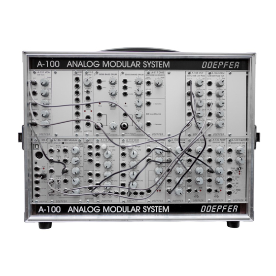
Mechanical and electrical conception
The modular system consists of a case (e.g. 19" case A-100G6 or one of the suitcase versions A-
100P6/P9 or one of the low-cost cases A-100LC6/LC9/LCB or one of the "monster" cases A-
100PMS6/PMS9/ PMS12/PMD12/PMB) and the modules that are installed into the case in question.
Each case contains one or more bus A-100 boards. The modules are connected to the bus boards via
ribbon cables. The bus is used to supply the modules with the required supply voltages. For some
modules the bus board can be used also to carry the CV and the Gate signal (for details please refer
to the user manuals of the modules in question).
Important note: A-100-modules have to be connected only to original A-100 bus boards or 100%
compatible bus boards of other manufacturers ! Particularly it's not allowed to use bus boards with
polarized pin headers (bowl pin headers with code gap). These may force the user to connect the bus
cable in a direction which might be the wrong one ! This will destroy the module and the warranty is
void ! In the A-100 the colored wire of the ribbon cable marks -12V and this wire has to point to the
bottom under all conditions !
Each case contains also one or more power supplies. The power supplies A-100PSU2 and A-
100PSU3 provide the supply voltages +12V and –12V that are required to run the A-100 modules. In
addition the A-100PSU3 has +5V available. Only a few older A-100 modules require +5V (e.g. A-190-
1, A-191 and A-113). But many modules from other manufacturers require +5V.
The power supply A-100PSU2 (used until end of 2015) outputs 1200 mA current at +12V and 1200
mA at –12V. The new power supply A-100PSU3 (used from end of 2015) has available 2000 mA at
+12V, 1200 mA at –12V and 4000 mA (4A) at +5V.
If you case contains the A-100PSU2 or A-100PSU3 can be recognized by the mains voltage label at
the rear panel. If the label says 230V or 115V the A-100PSU2 is built in. If the label says 100-240V
(wide range input) the A-100PSU3 is installed.
When a system is planned the sum of all module currents has to be less than the max. current of the
power supply (or supplies):
The cases A-100G6/P6/P9/LC6/LC9/LCB are equipped with one power supply (A-100PSU2 or
A-100PSU3).
The cases A-100PMS6/PMS9/PMB are equipped with two power supplies (A-100PSU2 or A-
100PSU3).
Case A-100PMS12 contains four power supplies (A-100PSU2 or A-100PSU3).
With the exception of a few very "exotic" module sets this is sufficient for all reasonable module
combinations.
In the monster cases A-100PMx the modules have to be distributed to the power supplies and bus
boards that the sum of all module currents has to be less than the max. current of the power supply in
question. With the exception of a few very "exotic" module sets this is sufficient for all reasonable
module combinations within the A-100. But one has to pay attention if modules from other
manufacturers are used that the max. current is not exceeded. Some of these modules have very high
current consumptions !
5

