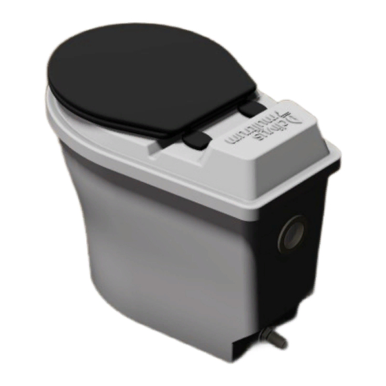
clivus multrum CM2 Manuale d'uso - Pagina 5
Sfoglia online o scarica il pdf Manuale d'uso per Servizi igienici clivus multrum CM2. clivus multrum CM2 13.

2.0 INSTALLATION
The following instructions relate to Figure 1 and are the recommended installation procedures. This may vary
depending on the location.
1.
Unpack the unit and remove all contents from the pedestal.
2.
Cut a 2" DWV PVC pipe to suit the thickness of your wall leaving sufficient length to connect the 2" Tee on the
outside.
3.
Insert the 2" DWV PVC pipe into the pedestal ventilation outlet. The Wallace seal for the vent outlet is pre-
greased for ease of insertion of the 50mm vent pipe.
4.
Position the pedestal with the rear against the wall.
5.
Mark the ventilation and drain outlet positions on the wall.
6.
Put the pedestal aside and drill through the wall for the drain pipe and ventilation pipe respectively.
NOTE:
The drain pipe exit hole must be lower than the pedestal outlet.
7.
Connect the drain hose to the pedestal using the hose barb and hose clamp.
8.
Return the pedestal to the wall. Place the 50mm floor flange supplied in the hole drilled in the wall for the vent
pipe. This gives it a tidy appearance. Feed the drain and vent pipe out through the wall. Using the mounting
blocks provided, fix the pedestal to the wall by screwing through the rear wall of the pedestal and through the
mounting blocks into the wall. At least 2 fixing points should be installed at a minimum of 100mm apart.
9.
Proceed to exterior piping installation. Connect the 2" Tee, 2" Cap and 4" to 2" Eccentric Reducer (including
12V DC fan) as shown in Figure 1 or Figure 2. Additional pipe may be required. Refer to Section 2.4.
NOTE:
Do not glue the Eccentric Reducer to the 4" 45° Elbow or 2" Tee to the 2" DWV pipe.
This allows for removal of the fan should it require replacement.
2.4
Ventilation Pipe
Air flow through the system is essential to the operation of the unit and care must be taken to ensure that the vent
line is installed correctly. The Ventilation system is used to help the composting process and to prevent odours from
escaping into the toilet room
Due to the variety of possible configurations, the vent kit supplied with your CM2 only includes the essential
components. Additional DWV pipe and fittings may be required for a complete installation.
The ventilation must be installed in accordance with AS 3500 Clause 6.7.4 where the pipe termination must be as
follows;
•
150mm above point of roof penetration.
•
600mm above any building opening that is within a horizontal distance of 3 meters.
•
600mm above any eave that is within 600mm from the vent.
The ventilation piping must be installed with a minimum grade of 1.25% sloping away from the pedestal and should be
as short as possible.
CM2 ventilation pipe break-out view Figure 3 next page...
OM-CM2.201104
Updated: 04/11/2018
Copyright © Ecoflo Wastewater Management
Page 5 of 13
