Cloud 50 Manuale di installazione e funzionamento - Pagina 3
Sfoglia online o scarica il pdf Manuale di installazione e funzionamento per Amplificatore Cloud 50. Cloud 50 14. 4 zone integrated mixer amplifier
Anche per Cloud 50: Manuale di installazione e funzionamento (13 pagine)
2
1
Safety Notes
• Do not expose the unit to water or moisture.
• Do not expose the unit to naked flames.
• Do not block or restrict any air vent.
• Do not operate the unit in ambient temperatures above 35 C.
• Do not touch any part or terminal carrying the hazardous live symbol (
while power is supplied to the unit.
• Do not perform any internal adjustments unless you are qualified to do so and fully
understand the hazards associated with mains operated equipment.
• The unit has no user serviceable parts. Refer any servicing to qualified service
personnel.
• If the moulded plug is cut off the lead for any reason, the discarded plug is a
potential hazard and should be disposed of in a responsible manner.
2
General
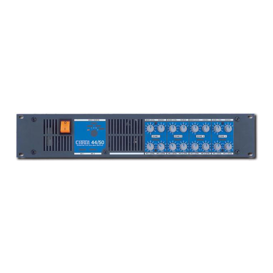
The Cloud 36/50 is a versatile, multi-source two zone mono mixer with integrated power
amplifiers. The 36/50 has one 50 watt power amplifier for each zone plus an additional 50
watt 'utility' output. The unit has applications where one microphone and six line level music
signals are required to feed up to three separate areas. A facility for connecting remote
controls for the music source and level are provided. For line distribution systems, optional
four channel 100V/70V line transformer modules are available.
The front panel controls are reduced to a minimum to reduce confusion; if preferred, the unit
can be positioned in a protected area with just the remote music level and source controls
positioned in the most appropriate location. All pre-set controls are on the rear panel. A
remote music mute facility is provided which may be used to satisfy the requirements of the
Local Fire Officer.
3
Schematic Diagram
06/12/02 V5.0
For more detailed information refer to the rear of the manual.
36/50: Installation and Operation Manual
o
)