Cloud CV8125 Manuale - Pagina 12
Sfoglia online o scarica il pdf Manuale per Unità di controllo Cloud CV8125. Cloud CV8125 15. Cv series
Anche per Cloud CV8125: Manuale di avvio rapido (13 pagine), Bollettino tecnico (13 pagine)
Architect's and Engineer's Specification
The power amplifiers shall be available in two channel, four
channel and eight channel versions. The output stage shall be
a transformerless constant voltage type suitable for driving
70 V-line or 100 V-line loudspeaker systems. Each amplifier shall
have two groups of channels with a total of 500 watts available
from each group: the even numbered channels shall form one group,
the odd channels a second group.
The amplifiers will include an automatic power-down (APD) feature
which will shut down either group of channels that has not received
an input signal for thirty minutes.
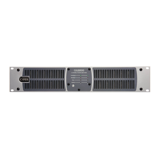
The amplifiers' front panels shall incorporate a "soft" AC power
switch, an LED indicating POWER ON, and LEDs indicating Signal
Present, Peak Level, Protect status and Power status for each
channel. The Signal Present LEDs shall illuminate when the output
level is 30 dB below the rated output. The Peak LEDs shall illuminate
at the onset of signal clipping. The Protect LEDs shall indicate
activation of the channel protection circuitry. The Power status LEDs
shall indicate that the channel has not been powered down by the
APD system.
The amplifiers shall be provided with a number of inputs equal to
the number of channels. The input connectors shall be of removable,
screw-terminal type. The inputs shall be electronically balanced and
capable of operating with both balanced and unbalanced sources.
The input impedance shall be 10 kohms (balanced). It shall be
possible to configure the amplifiers to operate in the following
configurations as a minimum: all channels independent, one input
feeding all channels or two inputs feeding the amplifier channels in
pairs for stereo operation. It shall be possible to enable a high-pass
3rd order filter with a turnover frequency of 65 Hz independently
in each amplifier channel. The amplifiers shall be provided with
externally accessible switches for setting each channel to operate
with 70 V-line or 100 V-line systems independently. It shall be
possible to select all the configurations and settings described in this
paragraph without accessing the interior of the amplifier enclosure,
and without connecting an external device.
Output level adjustment will be provided for each amplifier channel
via a rear panel control: at the minimum setting, the channel shall
be muted. Each channel shall deliver its rated power from an input
signal of 0 dBu with the channel level control set at maximum.
Output mute protection on power-up and thermal protection shall
be provided. The amplifiers will also be protected against short
circuits at the output, and excessive combination of output voltage
and current. The amplifiers' outputs shall be on removable, screw
terminal connectors.
The amplifiers shall include a digital signal processing (DSP) section:
this shall be controllable through a series of web pages stored
internally which shall be accessible on a web browser application
on an external computer or similar device connected to a standard
Ethernet port.
The DSP section shall provide the following facilities as a minimum:
i) configuration of amplifier channels for mono, stereo, mono or stereo
bi-amping with or without a separate LF sub output; the availability
of these configurations shall be restricted according to the number
of amplifier channels; ii) an input matrix section permitting any input
to feed any amplifier channel without restriction, iii) equalisation
for each channel: this shall have a minimum of seven bands and be
of the fully parametric type; the highest and lowest frequency bands
shall be selectable to bell or shelf modes; iv) a further equalisation
section for each channel capable of optimising the channel for use
with a selection of popular loudspeakers specific to commercial
sound applications by both the selection of a loudspeaker-specific
preset, and by the use of a equaliser of the parametric type with
a minimum of five frequency bands; v) a limiter section in each
channel, with threshold adjustment; vi) control of output level,
lowpass filtering and polarity of each auxiliary output.
There shall be at least two balanced line level auxiliary outputs on
removable, screw-terminal connectors. It shall be possible for the
source of each auxiliary output to be selectable from any of the
amplifier's main channels, and each output shall include the same
equalisation and limiter capabilities as the amplifier's main channels.
Each auxiliary output shall also include a filter section to permit the
configuration of loudspeaker crossover filters, with choice of filter
type and slope.
It shall be possible to apply a time delay to any or all channels and/
or auxiliary outputs. The total delay available shall not be less than
1.482 seconds, and it shall be possible to freely share this maximum
delay between all channels and/or auxiliary outputs. It shall be
possible to assign the delay in units of either time or distance (both
metric and imperial).
The amplifier shall maintain an internal log of amplifier power-
up and power-down times, occurrences of over-temperature, plus
impedance test results if the load monitoring option is fitted.
Load impedance monitoring shall be available as an option on all
versions. It shall be possible to specify test frequency for each
channel and also the dates and times of load testing.
An optional remote control shall be available for any or all amplifier
channels, to allow adjustment of channel level. The remote control
connector shall be of removable, screw-terminal type. The amplifiers
shall be equipped with a bi-directional serial control port to
RS-232C standards: all amplifier and DSP functions shall be
controllable via this port.
The amplifier shall be built in a steel chassis suitable for mounting in
a standard 19" equipment rack, and occupy two rack spaces. Variable
speed forced-air cooling shall be employed; the fan shall not operate
unless the internal temperature dictates it.
The amplifiers shall operate on all AC supply voltages between
85 V and 264 V. They shall be compliant with the relevant provisions
of EnergyStar® Eligibility Criteria Ver. 3.0 for Audio-Video Products.
In the absence of an input signal, they shall automatically enter
"standby" mode wherein the DC power consumption shall be less
than 3 W. It shall also be possible to control the power status of the
amplifiers via a dedicated control input with an external contact
closure.
The power amplifiers shall be the Cloud CV2500 (two channels),
CV4250 (four channels), and CV8125 (eight channels).The load
impedance monitoring option shall be the Cloud WM-2 (two
channels), WM-4 (four channels) and WM-8 (eight channels). The
remote level control plate shall be the Cloud RL-1 Series.
C l e a r l y b e t t e r s o u n d