Ashly MX-508 Manuale operativo - Pagina 5
Sfoglia online o scarica il pdf Manuale operativo per Mixer musicale Ashly MX-508. Ashly MX-508 16. 8-channel, mic/line mixer
Anche per Ashly MX-508: Note tecniche e specifiche (2 pagine), Manuale operativo (12 pagine), Manuale operativo (12 pagine), Scheda tecnica (2 pagine)

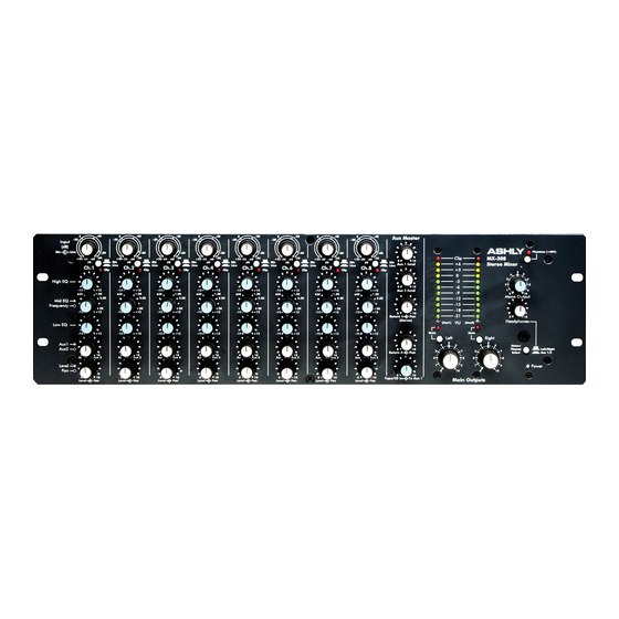
4.10 Output Meters
A pair of peak
reading 10 segment LED
meters are used to indicate
output level. Green LED's
are used below 0 VU, yel-
low above 0 VU and red
LED's indicate clipping. 0
VU is equivalent to +4 dBu
(1.228Vrms). This meter
pair is switchable (with the
headphone output) to either
the Main Left and Right
outputs or the Aux 1 and 2
outputs. The red clip LED's
will illuminate if the sum-
ming amplifiers are clip-
ping even if the main output
controls are off, in which
case one or more inputs
must be turned down. Note:
The output meters are accu-
rately calibrated to the
transformerless output lev-
els, but not necessarily the
transformer-balanced out-
puts. See note on Trans-
former Balanced Outputs.
4.11 Main Output Level
These controls de-
termine the level of both
transformer balanced and
transformerless output stages for the Main Left and Right
outputs.
4.12 Main Output Mutes
These switches turn off both the transformer-bal-
anced outputs as well as the transformerless 1/4" stereo
outputs, and indicate the mute mode by lighting the red
LED near the switch. The headphone and metering func-
tions continue uninterrupted even though there is no sig-
nal on the mixer's main outputs.
4.13 Phantom Power Switch
This front panel switch enables the 48 Volt phan-
tom power supply for condenser microphones which can
use this feature. One switch controls all the inputs. If you
have a mix of condenser and dynamic microphones, the
phantom power will not affect the operation of the dy-
namic mics.
Operating Manual - MX-508 Stereo Microphone/Line Mixer
Clip
+6
+3
0
-3
-6
-9
-12
-15
-18
-21
-L-
VU
(Aux1)
(Aux2)
Mute
Mute
Left
5
4
6
3
7
3
2
8
2
1
9
0
10
Main
Outputs
MX508
Stereo
Eight Channel
3
Mixer
2
1
Mono Output
Headphones
-R-
Meter/
Right
Phones
Select
5
4
6
7
8
1
9
0
10
Off
Power
4.14 Mono Output Level
This control adjusts the level of the summed mono
output. It is completely independent of the Main Left and
Right masters.
4.15 Headphones Level
This control adjusts the level of the designated
output signal (Mains or Aux) to the headphone jack.
4.16 Meter/Phones Select
This switch selects either the Main Left/Right
outputs or the Aux 1/Aux 2 outputs to the LED meters and
the headphone jack.
4.17 Headphone Output
This front panel 1/4" TRS connector feeds a stan-
dard set of stereo headphones. A selector switch that also
controls the level meter allows monitoring the main or Aux
outputs.
Phantom (+48V)
5
6
4
7
8
9
0
10
0
10
L/R
Aux 1/Aux 2
On
5
