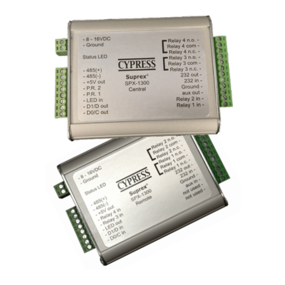
Cypress Suprex SPX-1300 Manuale operativo - Pagina 6
Sfoglia online o scarica il pdf Manuale operativo per Estensore Cypress Suprex SPX-1300. Cypress Suprex SPX-1300 17. Reader extender
Anche per Cypress Suprex SPX-1300: Manuale operativo (16 pagine)

Actual connections will differ based on the type of format, features utilized, and equipment interface.
The following diagrams are an example of a typical installation using the Suprex 1300 and a Wiegand format
Reader and Access Control Panel.
1. First connect units as shown below to verify basic function and communication. This should be done in a
convenient location such as a bench top before installing units in the field. Both units can share the same power
supply if the power supply has sufficient capacity.
When Connected as shown below, both units should have the Diagnostic LED flashing Green about 2-3 flashes
per second (Rapid flashing)
8 - 16 VDC
Power
Supply
8 - 16 VDC
Power
Supply
Suprex Operation and Initial Setup
+VDC
2-8 to 16 VDC In
1-Ground
Ground (0V)
8-485(+)
7-485(-)
6-+5 VDC Out
5-Prog Res 2
4-Prog Res 1
3-LED Input
2-D1/Data/F2F Out
1-D0/Clock Out
+VDC
2-8 to 16 VDC In
1-Ground
Ground (0V)
8-485(+)
7-485(-)
6-+5 VDC Out
5-RLY4 Input (5V)
4-RLY3 Input (5V)
3-LED Output
2-D1/Data/F2F Input
1-D0/CLK Input
Central Unit
*
1-D0/CLK Output
Remote Unit
*
12-RLY4 N.O.
11-RLY4 Com
10-RLY4 N.C.
9-RLY3 N.O.
8-RLY3 Com
7-RLY3 N.C.
6-RS232 Out
5-RS232 In
4-Ground
3-Aux Out
2-Relay2 Input
1-Relay1 Input
12-RLY2 N.O.
11-RLY2 Com
10-RLY2 N.C.
9-RLY1 N.O.
8-RLY1 Com
7-RLY1 N.C.
6-RS232 Out
5-RS232 In
4-Ground
3-Aux In
2-N/C
1-N/C
