- ページ 10
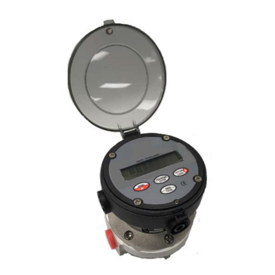
計測機器 Flomec D-40のPDF 取扱説明書をオンラインで閲覧またはダウンロードできます。Flomec D-40 15 ページ。 Oval gear medium capacity positive displacement pulse flowmeters 1/2”

4.2
Inspection (refer Exploded View) Inspect O-rings (3) for damage, chemical attack, deformity or any form.
Remove, inspect & clean the rotors (2), check that the primary rotor gear pinion for any damage. Check the
measuring chamber (1) for damage or scoring & redress if necessary, the rotor shafts should NOT be loose or
able to be rotated.
4.3
Re-assembly of meter (refer Exploded View) When re-installing the rotors (2) all four magnets MUST be
visible when both rotors are in place. Both rotors will only engage correctly if fitted precisely at an orientation of
90 degrees to each other. Rotate the rotors slowly by hand to ensure they are correctly fitted at the same time
check the rotor shafts & rotor bearings for wear.
Fit the O-ring (3) into the groove and assemble the two parts of the meter, the body (1) & cap (4) align with a
location pin.
Fit the body cap screws (5) and tighten in a star sequence then carryout a final tighten in the same sequence to
10 Nm (7.5 ft/lb).. This sequence and procedure ensures the meter bodies are assembled correctly and evenly.
Fit the pulse output board and instrument as appropriate.
This sequence and procedure ensures the meter bodies are assembled correctly and evenly. Once completed,
re-fit the totaliser assembly.
Maintenance
9
