- ページ 9
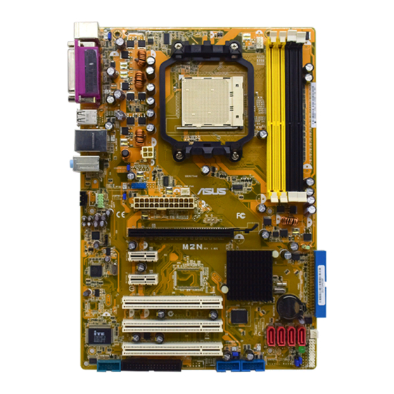
マザーボード AMD MCP61PのPDF ユーザーマニュアルをオンラインで閲覧またはダウンロードできます。AMD MCP61P 16 ページ。 Chipset m/b for amd socket am2/am2+ series processor
AMD MCP61P にも: ユーザーマニュアル (19 ページ)

2-3
Expansion Cards
MCP61P motherboard series offer one 16-LANE PCI-Express x16 graphics slot of 4Gbyte/sec
data transfer rate at each relative direction which get 3.5 times of bandwidth more than
AGP8X and it's up to a peak concurrent bandwidth of 8Gbyte/sec at full speed to guarantee
the performance and compatibility of GPU graphics add-in cards. The whole series carry two
32-bit PCI slots guarantee the rich connectivity for the I/O peripheral devices.
Connectors, Headers & Jumpers Setting
3-1 Connectors
(1)
Power Connector (24-pin block): ATXPWR1
ATX
Power
This is a new defined 24-pins
connector that usually comes with
ATX case. The ATX Power Supply
allows
using
momentary switch that connect from
the front panel switch to 2-pins
Power On jumper pole on the
motherboard.
switch on the back of the ATX
power supply turned on, the full
power will not come into the system
board until the front panel switch is
momentarily pressed.
switch again will turn off the power to the system board.
** We recommend that you use an ATX 12V Specification 2.0-compliant power supply
unit (PSU) with a minimum of 350W power rating. This type has 24-pin and 4-pin
power plugs.
Chapter 3
Supply
connector.
soft
power
on
When the power
Press this
ROW1 ROW2
ROW1 ROW2
Pin 1
Pin 1
24-Pin
20-Pin
7
PCI-E x16 by 16 lane
32-bit PCI Slot
PIN
ROW1
1
3.3V
3.3V
2
3.3V
-12V
3
GND
GND
4
5V
Soft Power On
5
GND
GND
6
5V
GND
7
GND
GND
8
Power OK
-5V
9
+5V (for Soft Logic)
+5V
10
+12V
+5V
11
+12V
+5V
12
+3V
GND
ROW2
