- ページ 4
サーバー Coachsound TourMaster-Lite TML2500のPDF インストレーション・マニュアルをオンラインで閲覧またはダウンロードできます。Coachsound TourMaster-Lite TML2500 11 ページ。 Two channel audio server
Coachsound TourMaster-Lite TML2500 にも: ユーザーマニュアル (15 ページ)

TourMaster-Lite Installation Guide v2.0
2 Head Unit
The purpose of the TourMaster-Lite System Head Unit is to receive a GPS signal and play appropriate commentary
over the existing audio system.
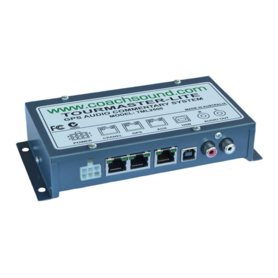
Head Unit Connections and Ports Diagram
LED status lights
•
"POWER" (CPANEL): This indicator is lit when power is present at the POWER connector.
•
"POWER" (GPS & AUX): These indicators are lit when the system is turned ON (via the control panel
or the PCON connections).
•
"LINK" (all ports): These indicators blink to indicate data activity on the port.
LED status lights are provided on the RJ45 ports. All ports are electrically protected; therefore if a "POWER"
indicator goes out when connecting a device to the head unit, then there is probably a fault with the device;
2.1 POWER Connection
10V-30V DC and GROUND (POWER) (Number 6):
These are the power supply connections to the system. Power should be connected to the ignition side of
the key (so power does not disconnect during engine cranking). To prevent flat batteries, the system
should be powered after any isolator switches so the system loses power when the isolator is turned off.
The system is internally over-current protected but external fuse protection is also recommended for
additional safety:
o
Recommended external fuse protection: 3 Amp
Maximum current (operational – ON via control panel): 1 Amp
o
Maximum current (shutdown – OFF via control panel): 100mA
o
Figure 1: Head Unit Connections and Ports Diagram
Figure 2: Power Connection
3
