- ページ 3
おもちゃ aero-naut Aero-MaxxのPDF 建築指示をオンラインで閲覧またはダウンロードできます。aero-naut Aero-Maxx 4 ページ。 Electric-powered rc model aircraft

Aero-Maxx
• Remove the rudder from the fin, and place it to one side for the moment.
• Insert the fin in the appropriate slots in the top of the fuselage. If it is too tight, open up the slots carefully.
• Check that the fin is at right-angles to the tailplane.
• Glue the fin to the fuselage permanently, again using thin cyano. Apply the adhesive exactly as described
for the tailplane.
• Glue the tailskid to the underside of the fuselage.
• The control surfaces should not be attached again until the model has been covered.
The canopy
• The canopy is removable, to ensure that you can swap batteries quickly at the flying field. All you have to
do is glue the vacuum-moulded plastic canopy to the plywood plate. The canopy can then be held in place
using a strip of adhesive tape for ease of removal and re-fitting.
• First remove the two plywood parts from the fuselage, then cover the opening in the fuselage with clear
plastic film so that the canopy cannot become stuck to the fuselage.
• Glue the two plywood parts together on the fuselage, taking care to position them accurately.
• Carefully cut out the canopy, working along the marked lines. Don't use large scissors for this; it is much
better to use nail scissors or special Lexan shears; these have curved blades and are available from most
model shops.
• Sand the cut edges smooth using fine glasspaper, and check that the canopy fits snugly and lines up
accurately with the fuselage shape. Take your time over this – a well-fitting canopy really looks good.
• The canopy can now be glued to the plywood frame using special plastic cement, although contact glue
can also be used (wet-on-wet). Tape the canopy to the fuselage until the glue has cured completely (!).
Covering
• We recommend translucent or solid-colour iron-on film for covering the model. If you have never used
iron-on film before, we recommend that you ask an experienced modeller to help you, otherwise you might
not obtain the results you wish.
• Sand the edges of the wingtips and all the edges of the tail surfaces to a rounded section. Use a sanding
block for this, clad with 180-grit abrasive paper or similar.
• Carefully remove all traces of dust from the model's components. Take care to avoid distorting (warping)
the components when you apply the iron-on film.
• Apply the film following the instructions supplied by the manufacturer.
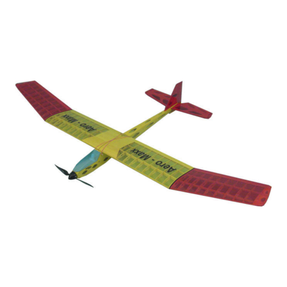
• We recommend that you use a darker colour on the outboard wing panels than on the centre section, as
the contrast will help you orientate the model in the air.
• The control surfaces can now be attached to the tailplane and fin using strips of adhesive tape as a hinge.
Ensure that they move freely to both sides of centre.
• Fit the hardwood dowels through the holes in the fuselage and glue them in place; they are used to secure
the wing retaining bands.
The motor
• The motor bulkhead is drilled to suit current 600-size electric motors. If you are using a brushed motor,
ensure that it is properly suppressed to prevent radio interference. The bulkhead is factory-installed at the
correct thrustline of 3° downthrust and 0° right sidethrust; these values have proved ideal over many test-
flights.
• Connect the motor to the speed controller, taking care to maintain correct polarity at the motor. Check the
direction of shaft rotation before you install the motor; drill a central hole in a small piece of wood and clamp
it on the motor shaft; this will help you detect the direction of rotation. Don't use the propeller for this –
injury hazard!
• Screw the motor to the motor bulkhead. Tighten the screws firmly, but not to the point where they
compress and damage the wood.
• Assemble and install the folding propeller, hub and spinner following the instructions supplied by the
manufacturer.
The radio control system
• The servos should be installed in the rear of the compartment under the wing; the aperture in the servo
plate suits most current 13 g servos. Secure the servos with the screws and fittings supplied with them.
• The steel pushrods feature a Z-bend at one end; this should be at the tail end of the fuselage.
• Connect the horn to the steel rod first, then slip the pushrod into the snake outer sleeve from the tail end of
the fuselage, and glue the horn to the control surface exactly in line with the snake outer. The job is easier if
you first mark the horn position on the rudder and elevator using a ruler.
3
Aero-Maxx building instructions
