コントロールユニット Ekinex EK-MC1-TPのPDF ユーザーマニュアルをオンラインで閲覧またはダウンロードできます。Ekinex EK-MC1-TP 2 ページ。
SBS S.p.A.
Via Circonvallazione s/n • 28010 MIASINO (NO) Italy • Tel. +39 0322.980909 • Fax +39 0322.980910
R&D Via Novara, 35 • 28010 VAPRIO D'AGOGNA (NO) Italy • Tel. +39 0321.966740 • Fax +39 0321.966997
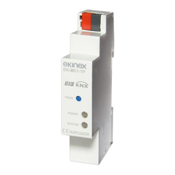
EK-MC1-TP
Modulo di comunicazione KNX
KNX communication module
I
- M A N U A L E D ' U S O
EN
- U S E R M A N U A L
ATTENZIONE!
L'installazione e l'utilizzo dello strumento devono essere effettuate esclusivamente da
personale qualificato. Togliere la tensione prima di intervenire sullo strumento.
WARNING!
Device installation and use must be carried out only by qualified staff.
Switch off the voltage before device installation.
DIMENSIONI (mm)
SIZE (mm)
90
25
44
18
PANORAMICA
OVERVIEW
+ -
COLLEGARE IL CONNETTORE KNX
KNX CONNECTOR WIRING
I
- ITALIANO
Effettuare i collegamenti sul connettore KNX come segue:
1.
Rimuovere 5 mm di isolamento di ogni singolo filo del doppino intrecciato TP (cavo
certificato EIB/KNX, fare riferimento al capitolo "Caratteristiche tecniche").
2.
Inserirlo nel connettore KNX fino a completo fissaggio, facendo attenzione a
rispettare la polarità (Rosso = +, Nero = -).
ATTENZIONE!
Il connettore KNX è dotato di due guide laterali che ne impediscono l'inserimento errato.
EN
- ENGLISH
For KNX connector wiring, refer to the following procedure:
45
1.
Remove 5 mm insulation from each single cable of TP twisted pair (EIB/KNX certified
cable, refer to the chapter "Technical features").
2.
Paying attention to connection polarity (Red = +, Black = -), plug it in the KNX
connector until complete fastening.
WARNING!
The KNX connector is provided with two side rails which prevent the wrong plug in.
65
Fare attenzione a rispettare la polarità dei collegamenti.
Pay attention to connection polarity!
A
I
- ITALIANO
A.
Connettore KNX. Rosso = +, Nero = -
B.
Porta ottica di comunicazione
B
C.
Tasto PROGRAMMAZIONE
D.
LED di alimentazione
C
E.
LED di comunicazione
D
E
EN
- ENGLISH
A.
KNX bus connector. Red = +, Black = -
B.
Optical COM port
PROGRAMMING key
C.
D.
Power supply LED
Communication LED
E.
5 mm
FUNZIONAMENTO DEL TASTO
KEY FUNCTIONALITY
I
- ITALIANO
Premere il tasto per almeno 2 s per abilitare la programmazione del modulo KNX. Il LED
di comunicazione inzierà a lampeggiare verde/rosso. A programmazione avvenuta, questa
modalità sarà disabilitata automaticamente. Se si desidera disabilitarla manualmente
senza effettuare la programmazione, premere nuovamente il tasto per almeno 2 s.
EN
- ENGLISH
Press the key for at least 2 s to enable the programming mode of KNX module. The
communication LED will start to blink green/red. After programming succeed, this
mode will be disabled automatically. To disable it manually without programming,
press again the key for at least 2 s.
FUNZIONAMENTO DEI LED
LEDS FUNCTIONALITY
I due LED sono presenti sul pannello frontale del modulo e consentono di segnalarne
lo stato di alimentazione e comunicazione.
Two LEDs are available on the module front panel to provide power supply and
communication status.
I
- ITALIANO
COLORE LED
SEGNALAZIONE
SIGNIFICATO
LED ALIMENTAZIONE
-
Spento
Modulo spento
VERDE
Sempre acceso
Modulo acceso
LED COMUNICAZIONE
-
Spento
Modulo spento
Lampeggio lento
Comunicazione KNX=OK
VERDE
(tempo spegnimento 2 s)
Comunicazione con il contatore=OK
Lampeggio veloce
Comunicazione KNX=fallita/mancante
ROSSO
(tempo spegnimento 1 s)
Comunicazione con il contatore=OK
ROSSO
Sempre acceso
Comunicazione con il contatore=fallita/mancante
VERDE/ROSSO
Colori alternati
Modalità programmazione abilitata
EN
- ENGLISH
LED COLOUR
SIGNALLING
MEANING
POWER SUPPLY LED
OFF
The module is OFF
-
GREEN
Always ON
The module is ON
COMMUNICATION LED
-
OFF
The module is OFF
Slow blink
KNX communication=OK
GREEN
(2 s OFF time)
Counter communication=OK
Fast blink
KNX communication=fault/missing
RED
(1 s OFF time)
Counter communication=OK
RED
Always ON
Counter communication=fault/missing
GREEN/RED
Alternating colours
Programming mode