- ページ 2
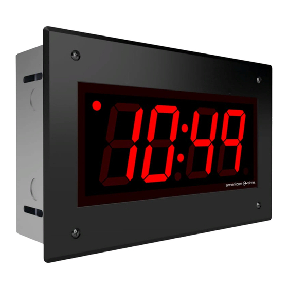
時計 American Time PGE261RFEのPDF クイック・スタート・インストール・マニュアルをオンラインで閲覧またはダウンロードできます。American Time PGE261RFE 2 ページ。 Flush-mount poe digital clock

Specifications
Weight
6.5 lbs (3 kg)
12.625" x 7.325" x 3.5" WxHxD (32 x
Box Dimensions
18.6 x 8.9 cm)
Faceplate Dimensions
13.5" x 8.5" WxH (34.3 x 21.6 cm)
Code Blue Current
3.0mA maximum at 12-30VAC/VDC
Operating Temperature
30°-104°F (0°-40°C)
95% relative humidity at 86°F (30° C)
Humidity
maximum, non-condensing
Display Modes
12-hour or 24-hour, user-configurable
Accuracy
±1 second
Electromagnetic Emissions
EN 55032:2012/AC:2013 Class B
Certifications
FCC 15.107:2018 Class B
FCC 15.109:2018 Class B
ICES-003:2016 Class B
Power Consumption (red digits)
Average
2.5" 6-digit
6.5W
4" 4-digit
5.5W
General Maintenance
American Time digital clocks require minimal maintenance. Cleaning should be done with
nothing more than a microfiber towel, moistened with water or a mild alcohol solution. No
abrasive materials should be used to clean the clock, as it will result in scratching of the
case or lens.
Avoid contact with the internal components of the clock when unpacking or preparing
for installation, or if the clock is disconnected after installation. Contact with the internal
components when the clock is not grounded can result in electrostatic discharge, which
could damage the clock.
PoE
Max
8.0W
7.0W
The flush-mount digital clock is designed to be mounted into a wall cavity, similar to a single
or double gang box. Ensure that installation conforms to the National Electrical Code and
local wiring codes.
NOTE: If installing the clock to be used with a Timer Control Station, the clock and TCS
must be no more than 30-ft apart.
CAUTION: Electric Shock Hazard!
Ensure that NO electrical power is
present on any wire before installation.
1. Remove the four sheet metal screws
(C) that hold the cover assembly (B)
and enclosure base (A) together. Be
sure to keep the sheet metal screws for
reassembly.
2. Mount the enclosure base (A) into the
wall by attaching the side of the back box
to a stud. Opening is 12.75" x 7.75" x
3.625".
If you are installing a Timer Control Station, proceed to Step 3. To finish clock installation
without a Timer Control Station, proceed to Step 6.
3. Pull the wiring from the Timer Control Station through the knockouts in the enclosure.
4. Connect the Timer Control Station wiring to the provided terminal plugs. See wiring detail
in the ATSTCS documentation for detailed wiring information.
5. Connect the terminal plug(s) to the terminal blocks on the clock as described in the
ATSTCS documentation.
6. Pull the CAT 5 or higher Ethernet cable (D) through a knockout in the enclosure.
7. Connect the Ethernet cable to the RJ45 jack on the clock's circuit board. The clock should
power on and obtain a connection, displaying a time within 45 seconds.
8. Re-attach the cover assembly (B) to the enclosure base (A) using the sheet metal screws
(C) removed in Step 1.
Installation
A
B
D
C
