- ページ 3
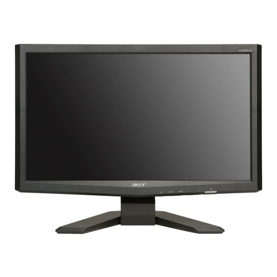
モニター Acer X193HQ SeriesのPDF サービスマニュアルをオンラインで閲覧またはダウンロードできます。Acer X193HQ Series 36 ページ。 Auo panel
Acer X193HQ Series にも: クイック・スタート・マニュアル (24 ページ), サービスマニュアル (47 ページ)

ACER X193HQ
2
Go to cover page
1.1 SCOPE
This document defines the design and performance
requirements for a 19W inch diagonal , flat panel monitor
.The display element shall be a WXGA(1366X768)
resolution TFT-LCD (Thin Film Transistor Liquid Crystal
Display).16.7M color images are displayed on the
panel.Video input signals are analog RGB (0.7Vp-p). When
the systemis powered-on , previously stored screen
parameters for a pre-defined mode will be recalled if the
operating mode is one of stored in memory( 21 factory , 9
users timing ).This monitor operates normal by non-
interlaced mode. DDC (Display Data Channel) function is
DDC2Bi compliance Power saving function complies with
the DPMS (Display Power Management Signaling)
standard.
1.2 GENERAL REQUIREMENTS
1.2.1Test Condition
Brightness level & contrast level max. Full white
pattern test mode following spec. Warm up more than
1 hr, ambient light < 10 Lux , Luminance meter
CA110 or BM7 or same equipment .
1.2.2 Test Equipment
The reference signal source is a calibrated Chroma
2135 video generator or higher.The use of other
signal generators during qualification and production
is acceptable provided the product complies with this
specification.
1.3 ELECTRICAL
This section describes the electrical requirement of the
monitor block diagram in Figure 1 illustrates the various
electrical sub-system.
1. Product Specification
The LCD monitor consists of an interface board , a power
board , a function key board and two speaker(1W)(with audio)
The interface board will house the flat panel control logic ,
brightness control logic, audio function control (option), key
function control, DDC and DC to DC conversion to supply the
appropriate power to the whole board and LCD flat panel , and
transmitting LVDS signals into LCD flat panel module to drive
the LCD display circuit .The power board will support main
power DC5V to interface board and drive the two CCFLs (Cold
Cathode Fluorescent Tube).The interface board provides the
power ON / OFF control over the whole monitor and control for
DPMS LED indicator to function key board.
Monitor Specifications
ITEM
Signal Input
(Analog)
Signal Input
(Digital)
Connector
Power Consumption
User'sControl
Pre-Defined Timing
Plug and Play
Power Saving
Input Signal Counter Tolerance
1.3.1 Interface Connectors
1.3.1.1 Power Connector and Cables
1.3.1.2 Video Signal Connectors and Cable
SPEC
Frequency
Analog
H:31Hz~83Hz
V:56Hz~75Hz
Pixel Clock
135MHz(Max)
Video Input
Analog :07Vp-p
640x480 (VGA)~1366x768(WXGA)
Display Pixels
Syne Signal
Separate SYNC for TTL (N or P)
Frequency
Digital
H:31Hz~83Hz
V:56Hz~75Hz
Pixel Clock
135MHz(Max)
Video Input
Analog :07Vp-p
Input Inpedance 75Ω
Display Pixels
640x480 (VGA)~1366x768(WXGA)
AC Input
AC 100V~AC240V 10% 50/60Hz ,3pin AC Power Cord
Input Connector
D-SUB 15 pin &DVI -D
Audio Jack(Optional )
Audio Input 3.6 Φ
AC in 100V~240V)
Active 30W(with Audio), active 25W ,Power Saving <2W
Front
Empowering ,Auto Adjust ,Adjust (-),Adjust (+),,Menu ,Power
OSD
Contrast,Brightness ,Position ,Clock ,Phase ,
Analog/Digital, RESET, Color ,Language select ,
Audio (Option ),ect.
Factory
21
User
9
VESA DDC 2Bi
VESA DPMS
≦H 1kHz,≦V 1Hz
The AC input shall have an IEC/CEE-22 type male
power receptacle for connection to mains power.
The power cord shall be with length of 1.8+/-0.005
meters.
The signal cable shall be 1.8
At the end of the cable shall be a molded-over,
shielded,triple row, 15 position, D-subminiature
connector. The CPU connection shall have captive
screw locks, which will be adequate for hand
tightening. The monitor connection may use small
screws.
Connector Pin Assignment
D-SUB
+/-
0.005 meters long.
