- ページ 10
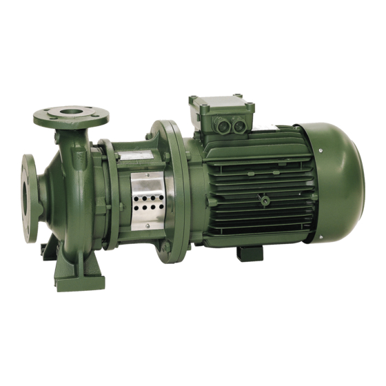
水ポンプ DAB NKM-G 80-200のPDF インストールとメンテナンスの手順をオンラインで閲覧またはダウンロードできます。DAB NKM-G 80-200 20 ページ。

13. MODIFICATIONS AND SPARE PARTS
Any modification not authorized beforehand relieves the manufacturer of all responsibility. All the spare parts used
in repairs must be original ones and the accessories must be approved by the manufacturer so as to be able to guarantee
maximum safety of persons and operators, and of the machines and systems in which they may be fitted.
14.
TROUBLESHOOTING
FAULT
1.
The motor does not start
and makes no noise.
2.
The motor does not start
but makes noise.
3.
The motor turns with
difficulty.
4.
The (external) motor
protection
trips
immediately
after
starting.
5.
The motor protection
trips too frequently.
6.
The pump does not
deliver.
7.
The pump does not
prime.
8.
The
pump
supplies
insufficient flow.
9.
Invert the connection of
two supply wires.
10. The pump turns in the
opposite direction when
switching off.
11. The pump vibrates and
operates noisily.
CHECK (possible cause)
A.
Check the protection fuses.
B.
Check the electric connections.
C.
Check that the motor is live
A.
Ensure that the mains voltage corresponds to the
voltage on the data plate.
B.
Check that the connections have been made
correctly.
C.
Check that all the phases are present on the
terminal board.
D.
The shaft is blocked. Look for possible obstructions
in the pump or motor.
A.
Check the supply voltage which may be
insufficient.
B.
Check whether any moving parts are scraping
against fixed parts.
C.
Check the state of the bearings.
A.
Check that all the phases are present on the
terminal board.
B.
Look for possible open or dirty contacts in the
protection.
C.
Look for possible faulty insulation of the motor,
checking the phase resistance and insulation to
earth.
D.
The pump is functioning above the work point for
which it was intended.
E.
The protection tripping values are wrong.
F.
The viscosity or density of the pumped fluid are
different from those used in the design phase.
A.
Ensure that the environment temperature is not too
high.
B.
Check the calibration of the protection.
C.
Check the state of the bearings.
D.
Check the motor rotation speed.
A.
The pump has not been correctly primed.
B.
Check that the direction of rotation of the three-
phase motors is correct.
C.
Difference in suction level too high.
D.
The diameter of the intake pipe is insufficient or the
length is too long.
E.
Foot valve blocked.
A.
The intake pipe or the foot valve is taking in air.
B.
The downward slope of the intake pipe favours the
formation of air pockets.
A.
Blocked foot valve.
B.
The impeller is worn or blocked.
C.
The diameter of the intake pipe is insufficient.
D.
Check that the direction of rotation is correct.
A.
Intake pressure too low.
B.
Intake pipe or pump partly blocked by impurities.
A.
Leakage in the intake pipe.
B.
Foot valve or check valve faulty or blocked in partly
open position.
A.
Check that the pump and/or the pipes are firmly
anchored.
B.
There is cavitation in the pump (see point 8,
paragraph on INSTALLATION).
C.
Presence of air in the pump or in the intake
manifold.
D.
Pump-motor alignment incorrectly performed.
ENGLISH
A.
If they are burnt-out, change them.
If the fault is repeated immediately this means that the
−
motor is short circuiting..
B. Correct any errors.
C. If not, restore the missing phase.
D. Remove the obstruction.
B.
Eliminate the cause of the scraping.
C.
Change any worn bearings.
A.
If not, restore the missing phase.
B.
Change or clean the component concerned.
C.
Look for possible faulty insulation of the motor, checking
the phase resistance and insulation to earth.
D.
Set the work point to suit the pump characteristics.
E.
Check the set values on the motor protector: alter them
or change the component if necessary.
F.
Reduce the flow rate with a shutter on the delivery side
or install a larger motor.
A.
Provide suitable ventilation in the environment where
the pump is installed.
B.
Calibrate at a current value suitable for the motor
absorption at full load.
C.
Change any worn bearings.
A.
Fill the pump and the intake pipe with water. Prime the
pump.
B.
Invert the connection of two supply wires.
C.
See point 8 of the instructions on "Installation".
D.
Replace the intake pipe with one with a larger diameter.
E.
Clean the foot valve.
A.
Eliminate the phenomenon, checking the intake pipe
accurately, and prime again.
B.
Correct the inclination of the intake pipe.
A.
Clean the foot valve.
B.
Change the impeller or remove the obstruction.
C.
Replace the pipe with one with a larger diameter.
D.
Invert the connection of two supply wires.
B.
Clean the intake pipe and the pump.
A.
Eliminate the fault.
B.
Repair or replace the faulty valve.
A.
Fasten any loose parts.
B.
Reduce the intake height or check for load losses. Open
the intake valve.
C.
Bleed the intake pipes and the pump.
D.
Repeat the procedure described in paragraph 7.2.
21
REMEDY
