- ページ 9
コントローラー Door Controls DC-ONE V3のPDF 入門およびトラブルシューティングマニュアルをオンラインで閲覧またはダウンロードできます。Door Controls DC-ONE V3 13 ページ。 Automatic door controller

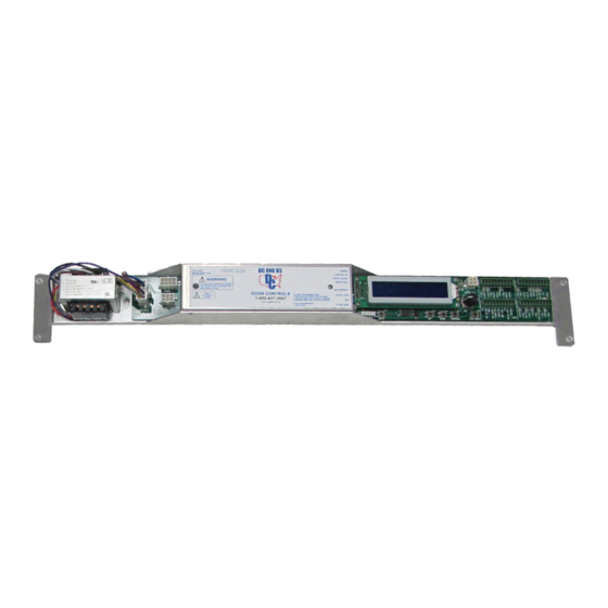
J6 – Safety Beams – Pins 7 to 10
Activates the door except when in the closed position
24 VAC power to safety beam module
Red LED is on when active
J5 – Inner and Outer Sensors
Separate 24 VAC connections for sensor power
Inner Sensor
o Activates door except when off or in night mode
o Green LED is on when active
Outer Sensor
o Activates door except in off, one way, or night mode
o Green LED is on when active
Safety
o Activates the door except when in the closed position
o Red LED is on when active
J7 – Special Modes
Emergency Open
o Activates the door during all modes
o Green LED is on when active
Ratchet
o Activates door and stays open until ratchet is pressed again
o Does not activate during off, one way, or night mode
o Green LED is on when active
Activation
o Activates the door during all modes
o Green LED is on when active
Breakout
o Stops door motion
o Software selectable polarity (NO/NC)
o Red LED is on when active
Night Mode
o Disables inner and outer sensors in closed position
o Door activates with emergency open and activation input only (pin 2 or 6 of J7)
o Yellow LED is on when active
J8 – Lock
Pins 1 to 6 are used to control the DC One lock
Lock voltage is selectable between 12 and 24 volts with toggle switch
See wiring diagrams for detailed information
CHECK TO ENSURE THAT ALL IS CLEAR AND READY TO OPERATE!PRESS THE TEST BUTTON ON THE
CONTROLLER. THE DOOR WILL MOVE THROUGH A LEARN CYCLE THEN REST IN THE CLOSED POSITION.
IF THE DOOR DOES NOT REST IN THE CLOSED POSITION GO BACK TO THE PROGRAMMING MENUS AND
CHANGE HANDING FROM LEFT TO RIGHT
