- ページ 5
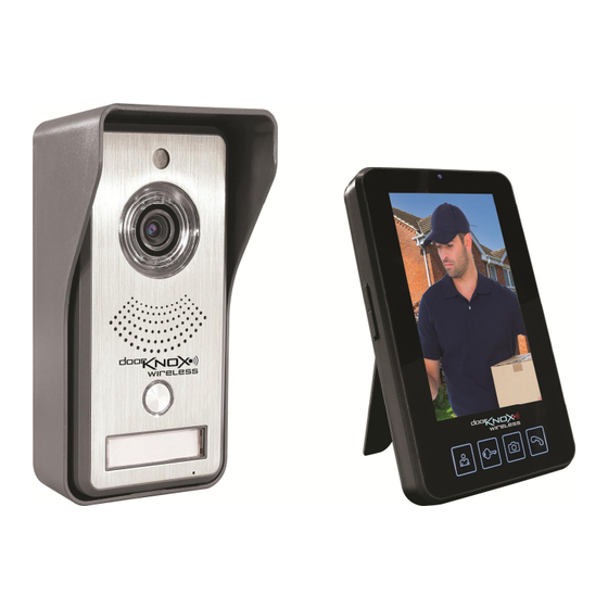
インターホン・システム Door Knox VDP400のPDF ユーザーマニュアルをオンラインで閲覧またはダウンロードできます。Door Knox VDP400 13 ページ。 Wireless external door entry kit

2. Wiring diagrams for magnetic lock and electric lock connections are shown below.
Connect electric lock to terminals 4 and 6 or connect a magnetic lock to terminals 5 and 6.
Note: When the camera is only powered by a lithium battery without any extra power supply,
the camera unit electric lock cannot be released.
Electric Lock
Magnetic Lock
Terminal
1
12v DC
2
0v
3
Door Release. Link to 0v to operate relay
4
Relay N.O (Normally Open)
5
Relay N.C (Normally Closed)
6
Relay Common
4. Install the weather shield at 1.5m-1.8m above ground level avoiding direct sunlight.
Email:
Function
Doc XVDP400
NOTE: Relay Contacts 3A 30v DC
Last Revised: 13/07/2017
