- ページ 3
キーパッド Door-Gard 2000eMのPDF インストールとプログラミングをオンラインで閲覧またはダウンロードできます。Door-Gard 2000eM 7 ページ。

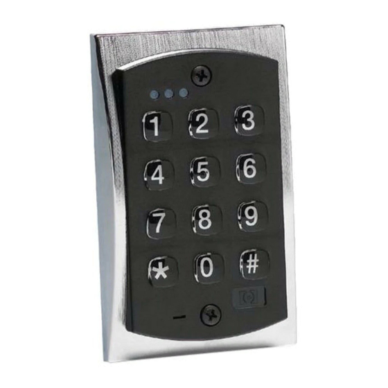
2000e & 2000eM Keypad Installation & Programming
Wiring a Maglock (Fail-Safe)
1.
Connect the red wire (V+) to the blue wire (common), and
then connect them to the positive on the power supply.
2.
Connect the gray wire (normally closed) to the positive on
the Maglock.
3.
Connect the black wire (V-) to the negative on the Maglock,
and then connect them both to the negative on the power
supply.
Wiring an Electric Door Strike (Fail-Secure)
1.
Connect the red wire (V+) to the blue wire (common), and
then connect them to the positive on the power supply.
2.
Connect the green wire (normally open) to the positive on
the strike.
3.
Connect the black wire (V-) to the negative on the strike, and
then connect them both to the negative on the power supply.
Shunting a Normally Closed Zone
1.
Connect the blue wire (common) to the common connection
on the door position switch.
2.
Connect the green wire (normally open) to the normally
closed connection on the door position switch.
6-104402 X2
Wiring the REX and Door Position Switch
1.
Connect the brown wire (REX Input) to the normally open
connection on the REX device.
2.
Connect the white/orange wire (loop common) to the
common on the REX device and the common on the door
switch.
3.
Connect the white wire (door loop) to the normally closed
connection on the door switch.
Note: By default, the forced door and propped door outputs are
assigned to the audio alerts. When you power up the keypad for the
fi rst time and door contacts are not connected, you may hear audio
alert #1 immediately followed by audio alert # 2 thirty seconds later. If
you are not using door contacts you must either short the white and
white/orange wires together or disable the audio alerts.
Secured Series Front End Wiring Diagram
To use the keypad as a Secured Series Front End, connect the red,
black, white/black and white/yellow wires, on the main keypad wire
harness, to the corresponding terminals on the Secured Series Door
Control Module. The drain wire must be connected at the controller
side only. Refer to the wiring distance and gauge in the specifi cations
chart.
Wiegand Front End Wiring Diagram
To use the keypad as a Wiegand Front End, connect the red, black
white/black, white/yellow and brown wires on the main keypad wire
harness to the corresponding terminals on the Wiegand Control
Panel. The drain wire must be connected at the panel side only. Refer
to the wiring distance and gauge in the specifi cations chart.
3
